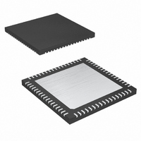
MAX4399CTK+ Maxim Integrated Products, MAX4399CTK+ Datasheet - Page 10

MAX4399CTK+
Manufacturer Part Number
MAX4399CTK+
Description
IC SW A/V SCART CON 68-TQFN
Manufacturer
Maxim Integrated Products
Type
Switchr
Datasheet
1.MAX4399CTKTD.pdf
(33 pages)
Specifications of MAX4399CTK+
Applications
Receivers, Set-Top Boxes, TV
Mounting Type
Surface Mount
Package / Case
68-TQFN Exposed Pad
Lead Free Status / RoHS Status
Lead free / RoHS Compliant
The MAX4399 audio/video switch matrix connects audio
and video signals between different ports. In the case of
a set-top box, the ports consist of the MPEG decoder
and three SCART connectors. For DVD+RW recorders
and some televisions, the ports consist of the main
board, front panel, tuner, and two SCART connectors.
The video section consists of input buffers, a crosspoint
switch, and output drivers that can be disabled. There
is also a mixer, which creates a composite video signal
from S-video. The video inputs can be set in either
clamp or bias mode. The red/chroma outputs have pull-
downs that connect the outputs to video ground as
described in the Video Inputs section.
The audio section features input buffers, a crosspoint
switch, and output drivers. The TV audio path has vol-
ume control from -56dB to +6dB in 2dB steps. The VCR
and AUX audio paths have volume control from -6dB to
+6dB in 6dB steps. The MAX4399 can be configured to
switch inputs during a zero crossing to reduce clicks.
The MAX4399 can also switch volume levels during a
zero crossing to reduce zipper noise. The audio out-
puts can operate in different modes. For instance, left
and right audio channels can be swapped (see the
Audio Outputs section).
Audio/Video Switch for Three SCART
Connectors
10
______________________________________________________________________________________
PIN
53
54
55
56
57
58
59
60
62
63
64
65
66
67
68
ENC_Y/CVBS_IN
AUX_Y/CVBS_IN
VCR_Y/CVBS_IN
TV_Y/CVBS_IN
AUX_R/C_IN
VCR_R/C_IN
ENC_R/C_IN
VCR_FS_IN
ENC_FS_IN
VCR_G_IN
ENC_G_IN
ENC_C_IN
VCR_B_IN
ENC_B_IN
ENC_Y_IN
NAME
Detailed Description
TV SCART Luma/Composite Video Input. Internally biased at 1.22V.
AUX SCART Red/Chroma Video Input. Internally biased at 1.22V for red, or 1.8V for chroma.
AUX SCART Luma/Composite Video. Internally biased at 1.22V.
VCR SCART Luma/Composite Video Input. Internally biased at 1.22V.
VCR SCART Fast-Switching Input
VCR SCART Red/Chroma Video Input. Internally biased at 1.22V for red, or 1.8V for chroma.
VCR SCART Green Video Input. Internally biased at 1.22V.
VCR SCART Blue Video Input. Internally biased at 1.22V.
Digital Encoder Luma/Composite Video Input. Internally biased at 1.22V.
Digital Encoder Red/Chroma Video Input. Internally biased at 1.22V for red, or 1.8V for
chroma.
Digital Encoder Green Video Input. Internally biased at 1.22V.
Digital Encoder Blue Video Input. Internally biased at 1.22V.
Digital Encoder Luma Video Input. Internally biased at 1.22V.
Digital Encoder Chroma Video Input. Internally biased at 1.8V.
Digital Encoder Fast-Switching Input
The MAX4399 has two fast-switching inputs and one
fast-switching output. Fast switching is used for creat-
ing on-screen displays by switching between the CVBS
and RGB signals. Under I
fast-switching output can follow either of the fast-
switching inputs or be set high or low.
The MAX4399 features three slow-switching input/out-
puts to support slow switching, which sets the screen
aspect ratio or video source of the display device. The
slow switching relies on tri-level logic in which the levels
are 0V, 6V, and 12V. The status of the slow-switching
input is continuously read and stored in register 0Eh. If
INTERRUPT_OUT is enabled, then INTERRUPT_OUT
changes to a high-impedance state if any of the slow-
switching inputs change logic levels. The slow-switching
outputs can be set to a logic level or high impedance by
writing to registers 07h, 09h, or 0Bh.
The MAX4399 can be configured through an I
patible interface. DEV_ADDR sets the I
address.
The MAX4399 triple SCART audio/video switch
includes multiplexed video amplifiers and a Y-C mixer-
driver with a trap filter to drive an RF modulator. The
MAX4399 switches video from an MPEG decoder out-
put and TV, VCR, and AUX SCART connectors.
FUNCTION
Pin Description (continued)
SCART Video Switching
2
C-compatible control, the
2
C-compatible
2
C-com-


