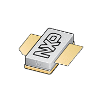
BLS6G3135S-120 NXP Semiconductors, BLS6G3135S-120 Datasheet - Page 7

BLS6G3135S-120
Manufacturer Part Number
BLS6G3135S-120
Description
120 W LDMOS power transistor intended for radar applications in the 3
Manufacturer
NXP Semiconductors
Datasheet
1.BLS6G3135S-120.pdf
(12 pages)
Available stocks
Company
Part Number
Manufacturer
Quantity
Price
Company:
Part Number:
BLS6G3135S-120
Manufacturer:
NXP
Quantity:
1 000
Company:
Part Number:
BLS6G3135S-120
Manufacturer:
NXP
Quantity:
5 000
NXP Semiconductors
8. Test information
BLS6G3135-120_6G3135S-120_2
Product data sheet
Table 9.
To ensure good power supply of the device, adding an electrolytical capacitor close to the supply
connection of the circuit may be required. The actual capacitor value may differ depending
on the pulse format, the quality of the power supply and the length of the connecting wires to the
power supply. In general a value of 470 F will be sufficient.
[1]
[2]
Component
C1, C2, C4, C5, C6,
C7, C8, C9, C11
C3
C10
C12
C13
L1
R1
R2
Fig 10. Component layout for 3.1 GHz to 3.5 GHz MHz test circuit
American Technical Ceramics type 100A or capacitor of same quality.
American Technical Ceramics type 700A or capacitor of same quality.
V
GG
Striplines are on a double copper-clad Rogers Duroid 6006 Printed-Circuit Board (PCB) with
See
r
= 6.2 and thickness = 0.64 mm.
List of components (see
C1
Table 9
R2
C3
BLS6G3135-120; BLS6G3135S-120
+
-
for list of components.
C4 C6
C5
R1
Description
multilayer ceramic chip capacitor
electrolytic capacitor
multilayer ceramic chip capacitor
multilayer ceramic chip capacitor
electrolytic capacitor
copper wire
resistor
SMD resistor
Rev. 02 — 29 May 2008
/ 4-line
C7
Figure
10)
LDMOS S-Band radar power transistor
/ 4-line
C8
C9
Value
24 pF
20 F; 20 V
33 pF
1 nF
100 F; 63 V
-
49.9
49.9
L1
C10
C2
C11
C12
V
© NXP B.V. 2008. All rights reserved.
DD
C13
[1]
[1]
[2]
+
-
Remarks
001aah591
7 of 12


