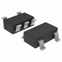
NCS2200SN2T1G ON Semiconductor, NCS2200SN2T1G Datasheet

NCS2200SN2T1G
Specifications of NCS2200SN2T1G
NCS2200SN2T1GOS
NCS2200SN2T1GOSTR
Available stocks
Related parts for NCS2200SN2T1G
NCS2200SN2T1G Summary of contents
Page 1
NCS2200 Series, NCS2200A Low Voltage Comparators The NCS2200 Series is an industry first sub−one volt, low power comparator family. These devices consume only supply current. They are guaranteed to operate at a low voltage of 0.85 V ...
Page 2
Table 1. Comparator Selector Guide Output Type Complementary Complementary Complementary Open Drain Open Drain Open Drain Open Drain Complementary Complementary 1 Output Non−Inverting 3 Input Style 1 Pinout (SN1T1) Figure 1. SOT−23−5 (NCS2200, NCS2202), SC70−5 (NCS2200, NCS2202) ...
Page 3
MAXIMUM RATINGS Rating Supply Voltage Range ( Non−inverting/Inverting Input Operating Junction Temperature Operating Ambient Temperature Storage Temperature Range Output Short Circuit Duration Time (Note 1) ESD Tolerance (Note 2) NCS2200 Human Body ...
Page 4
ELECTRICAL CHARACTERISTICS Characteristics Input Hysteresis T = 25°C A Input Offset Voltage 25° −40°C to 105° 3 25° −40°C to ...
Page 5
ELECTRICAL CHARACTERISTICS Characteristics Input Hysteresis T = 25°C A Input Offset Voltage 25° −40°C to 105° 3 25° −40°C to ...
Page 6
9.0 8.0 7.0 6.0 −50 − AMBIENT TEMPERATURE (°C) A Figure 1. NCS2200 Series Supply Current versus Temperature 12 10 8.0 6.0 4 85° ...
Page 7
T , AMBIENT TEMPERATURE (°C) A Figure 7. NCS2200 Series Output Voltage High State versus Temperature 700 600 t LH 500 400 t HL 300 200 T = ...
Page 8
T = 25°C A 2.0 1.0 0 −1.0 −2.0 −3.0 1.0 2.0 3.0 4 SUPPLY VOLTAGE (V) S Figure 13. NCS2200 Series Input Common Mode Voltage Range versus Supply Voltage 180 160 140 120 100 80 60 ...
Page 9
OPERATING DESCRIPTION The NCS2200 Series is an industry first sub−one volt, low power comparator family. This series is designed for rail−to−rail input and output performance. These devices consume only supply current while achieving a typical propagation delay ...
Page 10
M 100 The resistor divider R set the magnitude of the input pulse. The pulse width is set by adjusting C Figure 18. One−Shot Multivibrator http://onsemi.com ...
Page 11
100 k IN (−) NCS 100 k 2202 OUT IN (+) +5 V Logic Input This circuit converts 5 V logic logic. Using the NCS2202/3 allows for full 5 V logic swing without ...
Page 12
... ORDERING INFORMATION Device Pinout Style NCS2200AMUT1G N/A NCS2200SN1T1 1 NCS2200SN1T1G 1 NCS2200SN2T1 2 NCS2200SN2T1G 2 NCS2200SQ2T2 2 NCS2200SQ2T2G 2 NCS2200SQLT1 N/A NCS2200SQLT1G N/A NCS2202SN1T1 1 NCS2202SN1T1G 1 NCS2202SQ1T2G 1 NCS2202SN2T1 2 NCS2202SN2T1G 2 NCS2202SQ2T2G 2 This device contains 93 active transistors. †For information on tape and reel specifications, including part orientation and tape sizes, please refer to our Tape and Reel Packaging Specifications Brochure, BRD8011/D ...
Page 13
SOT−23−5 (TSOP−5) SN SUFFIX CASE 483 5 CAx AYWG for NCS2200SN1T1 J for NCS2200SN2T1 M for NCS2202SN1T1 N for NCS2202SN2T1 A = Assembly Location Y = Year W = Work Week G = Pb−Free Package ...
Page 14
... A C SEATING 0.05 PLANE H T *For additional information on our Pb−Free strategy and soldering details, please download the ON Semiconductor Soldering and Mounting Techniques Reference Manual, SOLDERRM/D. PACKAGE DIMENSIONS SOT−23−5 / TSOP−5 / SC59−5 SN SUFFIX PLASTIC PACKAGE CASE 483−02 ISSUE H ...
Page 15
... *For additional information on our Pb−Free strategy and soldering NOTE 3 0.05 C details, please download the ON Semiconductor Soldering and Mounting Techniques Reference Manual, SOLDERRM/D. EXPOSED Cu É É É É A3 É É DETAIL B Side View (Optional) http://onsemi.com 15 NOTES: 1 ...
Page 16
... C H SOLDERING FOOTPRINT* 0.50 0.0197 0.40 0.0157 *For additional information on our Pb−Free strategy and soldering details, please download the ON Semiconductor Soldering and Mounting Techniques Reference Manual, SOLDERRM/D. SQ SUFFIX CASE 419A−02 ISSUE J NOTES: 1. DIMENSIONING AND TOLERANCING PER ANSI Y14.5M, 1982. 2. CONTROLLING DIMENSION: INCH. ...
Page 17
... L 5X 0.40 PITCH *For additional information on our Pb−Free strategy and soldering details, please download the ON Semiconductor Soldering and Mounting Techniques Reference Manual, SOLDERRM/D. N. American Technical Support: 800−282−9855 Toll Free USA/Canada Europe, Middle East and Africa Technical Support: Phone: 421 33 790 2910 Japan Customer Focus Center Phone: 81− ...


