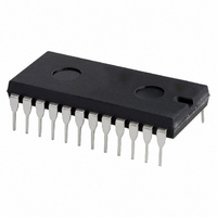
74HC4059N,112 NXP Semiconductors, 74HC4059N,112 Datasheet - Page 12

74HC4059N,112
Manufacturer Part Number
74HC4059N,112
Description
IC PROG DIV-BY-N COUNTER 24-DIP
Manufacturer
NXP Semiconductors
Series
74HCr
Datasheet
1.74HCT4059D112.pdf
(20 pages)
Specifications of 74HC4059N,112
Package / Case
24-DIP (0.600", 15.24mm)
Logic Type
Divide-by-N
Direction
Down
Number Of Elements
1
Number Of Bits Per Element
16
Reset
Asynchronous
Timing
Synchronous
Count Rate
43MHz
Trigger Type
Positive Edge
Voltage - Supply
2 V ~ 6 V
Operating Temperature
-40°C ~ 125°C
Mounting Type
Through Hole
Counter Type
Decade Counters
Logic Family
74HC
Counting Method
Synchronous
Counting Sequence
Down
Operating Supply Voltage
2 V to 6 V
Operating Temperature Range
- 40 C to + 125 C
Mounting Style
SMD/SMT
Lead Free Status / RoHS Status
Lead free / RoHS Compliant
Lead Free Status / RoHS Status
Lead free / RoHS Compliant, Lead free / RoHS Compliant
Other names
74HC4059N
74HC4059N
933757400112
74HC4059N
933757400112
Philips Semiconductors
APPLICATION INFORMATION
Calculating the minimum and maximum divide-by-n
values:
Output frequency range = 87.6 to 103.8 MHz
(CCIR band 2)
Channel spacing frequency (f
Division factor prescaler (k) = 10
Reference frequency (f
Maximum divide-by-n value =
Minimum divide-by-n value =
Fixed divide-by-n value =
Application of the “4059” as divide-by-n counter allows
programming of the channel spacing (shown in equations
as 300 kHz). A channel in the CCIR band 2 is selected by
the divide-by-n counter as follows:
channel = n
1998 Jul 08
Programmable divide-by-n counter
Fig.10 Example showing the application of the PC74HC/HCT4059 in a phase-locked-loop (PLL) for a FM band
synthesizer.
290
r
) =
----------------- -
30 kHz
3 MHz
f
--- -
k
c
c
87.6 MHz
------------------------ -
=
) = 300 kHz
103.8 MHz
---------------------------- -
300 kHz
300 kHz
300
--------- -
10
=
100
=
30 kHz
=
=
292
346
12
Figure 11 shows a BCD switch compatible arrangement
suitable for divide-by-5 and divide-by-8 modes, which can
be adapted (with minimal changes) to the other
divide-by-modes. In order to be able to preset to any
number from 3 to 256 000, while preserving the BCD
switch compatible character of the JAM inputs, a rather
complex cascading scheme is necessary because the
“4059” can never be preset to count less than 3. Logic
circuitry is required to detect a condition where one of the
numbers to be preset in the “4059” is 3. In order to
simplify the detection logic, only that condition is detected
where the JAM inputs to terminals 6, 7 and 9 would be
LOW during one count. If such a condition is detected, and
if at least 1 is expected to be jammed into the MSB
counter, the detection logic removes one from the number
to be jammed into the MSB counter (with a place value of
2 000 times the divide-by-mode) and jams the same 2 000
into the “4059” by forcing pins 6, 7 and 9 HIGH.
The general circuit in Fig.11 can be simplified considerably
if the range of the cascaded counters do not start at a very
low value.
Figure 12 shows an arrangement in the divide-by-4 mode,
where the counting range extends in a BCD switch
compatible manner from 99 003 to 114 999.
74HC/HCT4059
Product specification


