SY89840UMG Micrel Inc, SY89840UMG Datasheet - Page 10
SY89840UMG
Manufacturer Part Number
SY89840UMG
Description
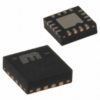
IC MUX 2:1 LVPECL DIFF 16MLF
Manufacturer
Micrel Inc
Series
SY89r
Type
Multiplexerr
Datasheet
1.SY89840UMG.pdf
(15 pages)
Specifications of SY89840UMG
Circuit
1 x 2:1
Independent Circuits
1
Voltage Supply Source
Single Supply
Voltage - Supply
3 V ~ 3.6 V
Operating Temperature
-40°C ~ 85°C
Mounting Type
Surface Mount
Package / Case
16-MLF®, QFN
Number Of Clock Inputs
2
Mode Of Operation
Differential
Output Logic Level
LVPECL
Operating Supply Voltage (min)
2.375V
Operating Supply Voltage (typ)
2.5/3.3V
Operating Supply Voltage (max)
3.6V
Package Type
MLF
Operating Temp Range
-40C to 85C
Operating Temperature Classification
Industrial
Signal Type
CML/LVDS/PECL
Mounting
Surface Mount
Pin Count
16
Lead Free Status / RoHS Status
Lead free / RoHS Compliant
Current - Output High, Low
-
Lead Free Status / Rohs Status
Compliant
Other names
576-1434
Available stocks
Company
Part Number
Manufacturer
Quantity
Price
Company:

Part Number:
SY89840UMG
Manufacturer:
MICREL
Quantity:
33


February 2005
Case #4 Input Clock Failure: Switching from the
selected clock input stuck in an undetermined state
to a valid clock input (RPE enabled).
If CLK1 fails to an undetermined state (e.g.,
amplitude falls below the 100mV (V
single-ended input limit, or 200mV differentially)
before the RPE MUX selects CLK2 (using the SEL
pin), the switchover to the valid clock CLK2 will
occur either following Case #2 or Case #3,
depending on the last valid state at the CLK1.
If the selected input clock fails to a floating, static, or
extremely low signal swing, including 0mV, the FSI
Power-On Reset (POR) Description
The SY89840U includes an internal power-on reset
(POR) function to ensure the RPE logic starts-up in
a known logic state once the power-supply voltage is
stable. An external capacitor connected between
V
the power-on reset function.
Calculation of the required capacitor value is based
on the time the system power supply needs to power
up to a minimum of 2.3V. The time constant for the
internal power-on-reset must be greater than the
time required for the power supply to ramp up to a
minimum of 2.3V.
CC
and the CAP pin (pin 11) controls the delay for
IN
) minimum
Timing Diagram 4
10
function will eliminate any metastable condition and
guarantee a stable output signal. No ringing and no
undetermined state will occur at the output under
these conditions.
Please note that the FSI function will not prevent
duty cycle distortions or runt pulses in case of a
slowly deteriorating (but still toggling) input signal.
Due to the FSI function, the propagation delay will
depend on rise and fall time of the input signal and
on its amplitude. Refer to “Typical Operating
Characteristics” for more detailed information.
The following equation describes this relationship:
As an example, if the time required for the system
power supply to power up past 2.3V is 12ms, the
required capacitor value on pin 11 would be:
C(μF)
C(μF) ≥
C(μF) ≥
≥
12
t
(
dPS
12
hbwhelp@micrel.com
ms
1
μ
(
(
F
ms
12
/
ms
μ
ms
)
F
/
)
μ
F
)
or (408) 955-1690
M9999-021705
Related parts for SY89840UMG
Image
Part Number
Description
Manufacturer
Datasheet
Request
R

Part Number:
Description:
3.3V 800MHz Ultrasmall Dual LVTTL-to-LVPECL Translator (I Temp, Green)
Manufacturer:
Micrel Inc
Datasheet:

Part Number:
Description:
IC XPOINT SW 4X4 PREC 44-MLF
Manufacturer:
Micrel Inc
Datasheet:
Part Number:
Description:
IC XPOINT SWITCH 3.2GBPS 44-MLF
Manufacturer:
Micrel Inc
Datasheet:
Part Number:
Description:
IC XPOINT SWITCH 3.2GBPS 44-MLF
Manufacturer:
Micrel Inc
Datasheet:
Part Number:
Description:
IC XPOINT SWITCH 4X4 LVDS 44-MLF
Manufacturer:
Micrel Inc
Datasheet:
Part Number:
Description:
IC XPOINT SWITCH 4X4 LVDS 44-MLF
Manufacturer:
Micrel Inc
Datasheet:

Part Number:
Description:
IC MUX 2:1 LVPECL RPE/FSI 16MLF
Manufacturer:
Micrel Inc
Datasheet:
Part Number:
Description:
IC MUX 2:1 LVDS RPE 16-MLF
Manufacturer:
Micrel Inc
Datasheet:
Part Number:
Description:
IC MUX 8:1 PREC LP 44-MLF
Manufacturer:
Micrel Inc
Datasheet:

Part Number:
Description:
IC MUX 2:1 LVDC DUAL 3.3V 32MLF
Manufacturer:
Micrel Inc
Datasheet:
Part Number:
Description:
IC MUX 4:1 LVDS DIFF 2.5V 32MLF
Manufacturer:
Micrel Inc
Datasheet:
Part Number:
Description:
IC MUX 4:1 LVDS DIFF 3.3V 32MLF
Manufacturer:
Micrel Inc
Datasheet:
Part Number:
Description:
IC MUX 4:1 LVDS DIFF 2.5V 32MLF
Manufacturer:
Micrel Inc
Datasheet:
Part Number:
Description:
IC MUX 4:1 LVDS DIFF 3.3V 32MLF
Manufacturer:
Micrel Inc
Datasheet:
Part Number:
Description:
IC MUX 8:1 LP 1:2 LVPECL 44MLF
Manufacturer:
Micrel Inc
Datasheet: