CAT24C128WI-GT3 ON Semiconductor, CAT24C128WI-GT3 Datasheet - Page 7
CAT24C128WI-GT3
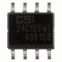
Manufacturer Part Number
CAT24C128WI-GT3
Description
IC EEPROM 128KBIT 400KHZ 8SOIC
Manufacturer
ON Semiconductor
Datasheet
1.CAT24C128WI-GT3.pdf
(14 pages)
Specifications of CAT24C128WI-GT3
Format - Memory
EEPROMs - Serial
Memory Type
EEPROM
Memory Size
128K (16K x 8)
Speed
400kHz
Interface
I²C, 2-Wire Serial
Voltage - Supply
1.8 V ~ 5.5 V
Operating Temperature
-40°C ~ 85°C
Package / Case
8-SOIC (3.9mm Width)
Density
128Kb
Interface Type
Serial (I2C)
Organization
16Kx8
Access Time (max)
900ns
Frequency (max)
400KHz
Write Protection
Yes
Data Retention
100Year
Operating Supply Voltage (typ)
2.5/3.3/5V
Package Type
SOIC
Operating Temp Range
-40C to 85C
Supply Current
3mA
Operating Supply Voltage (min)
1.8V
Operating Supply Voltage (max)
5.5V
Operating Temperature Classification
Industrial
Mounting
Surface Mount
Pin Count
8
Lead Free Status / RoHS Status
Lead free / RoHS Compliant
Other names
24C128WI-GT3
CAT24C128WI-GT3TR
CAT24C128WI-GT3TR
Available stocks
Company
Part Number
Manufacturer
Quantity
Price

Part Number:
CAT24C128WI-GT3
Manufacturer:
ON
Quantity:
20 000


Read Operations
Immediate Read
the CAT24C128 will interpret this as a request for data
residing at the current byte address in memory. The
CAT24C128 will acknowledge the Slave address, will
immediately shift out the data residing at the current address,
and will then wait for the Master to respond. If the Master
does not acknowledge the data (NoACK) and then follows
up with a STOP condition (Figure 10), the CAT24C128
returns to Standby mode.
Selective Read
address counter must first be initialized as described under
Byte Write. If rather than following up the two address bytes
BUS ACTIVITY:
Upon receiving a Slave address with the R/W bit set to ‘1’,
To read data residing at a specific location, the internal
MASTER
P v 63
* = Don’t Care Bit
SLAVE
S
R
S
T
A
T
ADDRESS
SDA
SCL
SLAVE
WP
a
1
7
A
C
K
* *
ADDRESS
ADDRESS
a
BYTE
BYTE
13
−a
8
Figure 8. Page Write Sequence
A
C
K
8
a
0
Figure 9. WP Timing
ADDRESS
http://onsemi.com
BYTE
a
7
−a
t
SU:WP
0
9
7
C
A
K
with data, the Master instead follows up with an Immediate
Read sequence, then the CAT24C128 will use the 14 active
address bits to initialize the internal address counter and will
shift out data residing at the corresponding location. If the
Master does not acknowledge the data (NoACK) and then
follows up with a STOP condition (Figure 11), the
CAT24C128 returns to Standby mode.
Sequential Read
data byte, then the CAT24C128 will continue transmitting
data residing at subsequent locations until the Master
responds with a NoACK, followed by a STOP (Figure 12).
In contrast to Page Write, during Sequential Read the
address count will automatically increment to and then
wrap−around at end of memory (rather than end of page).
If during a Read session the Master acknowledges the 1
t
HD:WP
DATA
BYTE
d
n
1
7
A
C
K
DATA
BYTE
DATA
BYTE
n+1
d
8
0
C
A
K
A
C
K
DATA
BYTE
n+P
A
C
K
O
S
T
P
P
st
Related parts for CAT24C128WI-GT3
Image
Part Number
Description
Manufacturer
Datasheet
Request
R

Part Number:
Description:
ON Semiconductor [VOLTAGE REGULATOR]
Manufacturer:
ON Semiconductor
Datasheet:
Part Number:
Description:
357-036-542-201 CARDEDGE 36POS DL .156 BLK LOPRO
Manufacturer:
ON Semiconductor
Datasheet:
Part Number:
Description:
357-036-542-201 CARDEDGE 36POS DL .156 BLK LOPRO
Manufacturer:
ON Semiconductor
Datasheet:
Part Number:
Description:
357-036-542-201 CARDEDGE 36POS DL .156 BLK LOPRO
Manufacturer:
ON Semiconductor
Datasheet:
Part Number:
Description:
357-036-542-201 CARDEDGE 36POS DL .156 BLK LOPRO
Manufacturer:
ON Semiconductor
Datasheet:
Part Number:
Description:
357-036-542-201 CARDEDGE 36POS DL .156 BLK LOPRO
Manufacturer:
ON Semiconductor
Datasheet:
Part Number:
Description:
357-036-542-201 CARDEDGE 36POS DL .156 BLK LOPRO
Manufacturer:
ON Semiconductor
Datasheet:
Part Number:
Description:
357-036-542-201 CARDEDGE 36POS DL .156 BLK LOPRO
Manufacturer:
ON Semiconductor
Datasheet:
Part Number:
Description:
357-036-542-201 CARDEDGE 36POS DL .156 BLK LOPRO
Manufacturer:
ON Semiconductor
Datasheet:
Part Number:
Description:
357-036-542-201 CARDEDGE 36POS DL .156 BLK LOPRO
Manufacturer:
ON Semiconductor
Datasheet:
Part Number:
Description:
357-036-542-201 CARDEDGE 36POS DL .156 BLK LOPRO
Manufacturer:
ON Semiconductor
Datasheet:
Part Number:
Description:
Manufacturer:
ON Semiconductor
Datasheet:
Part Number:
Description:
Manufacturer:
ON Semiconductor
Datasheet:
Part Number:
Description:
Manufacturer:
ON Semiconductor
Datasheet: