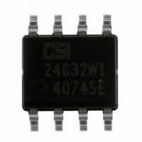
CAT24C32WI-G ON Semiconductor, CAT24C32WI-G Datasheet - Page 8

CAT24C32WI-G
Manufacturer Part Number
CAT24C32WI-G
Description
IC EEPROM 32KBIT 400KHZ 8SOIC
Manufacturer
ON Semiconductor
Datasheet
1.CAT24C32YI-GT3.pdf
(16 pages)
Specifications of CAT24C32WI-G
Format - Memory
EEPROMs - Serial
Memory Type
EEPROM
Memory Size
32K (4K x 8)
Speed
400kHz
Interface
I²C, 2-Wire Serial
Voltage - Supply
1.8 V ~ 5.5 V
Operating Temperature
-40°C ~ 85°C
Package / Case
8-SOIC (3.9mm Width)
Organization
128 K Pages x 256
Interface Type
I2C
Maximum Clock Frequency
0.1 MHz
Access Time
3500 ns
Supply Voltage (max)
5.5 V
Supply Voltage (min)
1.7 V
Maximum Operating Current
2 mA
Maximum Operating Temperature
+ 85 C
Mounting Style
SMD/SMT
Minimum Operating Temperature
- 40 C
Operating Supply Voltage
1.8 V , 2.5 V , 3.3 V , 5 V
Lead Free Status / RoHS Status
Lead free / RoHS Compliant
Available stocks
Company
Part Number
Manufacturer
Quantity
Price
Part Number:
CAT24C32WI-G
Manufacturer:
ON/安森美
Quantity:
20 000
Company:
Part Number:
CAT24C32WI-GT3
Manufacturer:
CATALYST
Quantity:
3 515
Part Number:
CAT24C32WI-GT3
Manufacturer:
ON/安森美
Quantity:
20 000
Company:
Part Number:
CAT24C32WI-GT3JN
Manufacturer:
ON Semiconductor
Quantity:
2 200
Immediate Read
condition on the bus and then broadcasts a Slave address
with the R/W bit set to ‘1’. The Slave responds with ACK
and starts shifting out data residing at the current address.
After receiving the data, the Master responds with NoACK
and terminates the session by creating a STOP condition on
the bus (Figure 10). The Slave then returns to Standby mode.
Selective Read
address must first be loaded into the internal address register.
This is done by starting a Byte Write sequence, whereby the
Master creates a START condition, then broadcasts a Slave
address with the R/W bit set to ‘0’ and then sends two
address bytes to the Slave. Rather than completing the Byte
To read data from memory, the Master creates a START
To read data residing at a specific address, the selected
BUS ACTIVITY:
BUS ACTIVITY:
MASTER
MASTER
SLAVE
SLAVE
SCL
SDA
S
S
T
A
R
T
ADDRESS
SLAVE
ADDRESS
SLAVE
A
C
K
BUS ACTIVITY
Figure 10. Immediate Read Sequence and Timing
A
C
K
BYTE
DATA
MASTER
n
Figure 12. Sequential Read Sequence
SLAVE
Figure 11. Selective Read Sequence
ADDRESS
DATA OUT
BYTE
8th Bit
8
READ OPERATIONS
A
C
K
R
S
S
T
A
T
http://onsemi.com
ADDRESS
BYTE
DATA
A
C
K
SLAVE
n+1
ADDRESS
8
BYTE
Write sequence by sending data, the Master then creates a
START condition and broadcasts a Slave address with the
R/W bit set to ‘1’. The Slave responds with ACK after every
byte sent by the Master and then sends out data residing at
the selected address. After receiving the data, the Master
responds with NoACK and then terminates the session by
creating a STOP condition on the bus (Figure 11).
Sequential Read
responds with ACK, then the Slave will continue
transmitting until the Master responds with NoACK
followed by STOP (Figure 12). During Sequential Read the
internal byte address is automatically incremented up to the
end of memory, where it then wraps around to the beginning
of memory.
A
C
K
If, after receiving data sent by the Slave, the Master
A
C
K
NO ACK
9
BYTE
DATA
A
C
K
BYTE
DATA
n+2
S
S
T
A
R
T
ADDRESS
SLAVE
A
C
K
N
O
C
A
K
P
O
S
T
P
A
C
K
STOP
BYTE
DATA
n+x
BYTE
DATA
O
N
A
C
K
O
S
P
P
T
O
N
A
C
K
O
S
T
P
P


