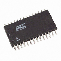
AT27C512R-15RI Atmel, AT27C512R-15RI Datasheet - Page 3

AT27C512R-15RI
Manufacturer Part Number
AT27C512R-15RI
Description
IC OTP 512KBIT 150NS 28SOIC
Manufacturer
Atmel
Datasheet
1.AT27C512R-70PU.pdf
(15 pages)
Specifications of AT27C512R-15RI
Format - Memory
EPROMs
Memory Type
OTP EPROM
Memory Size
512K (64K x 8)
Speed
150ns
Interface
Parallel
Voltage - Supply
4.5 V ~ 5.5 V
Operating Temperature
-40°C ~ 85°C
Package / Case
28-SOIC (8.69mm width)
Lead Free Status / RoHS Status
Contains lead / RoHS non-compliant
Other names
AT27C512R15RI
Available stocks
Company
Part Number
Manufacturer
Quantity
Price
Company:
Part Number:
AT27C512R-15RI
Manufacturer:
ATMEL
Quantity:
2
Part Number:
AT27C512R-15RI
Manufacturer:
ATMEL/爱特梅尔
Quantity:
20 000
3. System Considerations
4. Block Diagram
5. Absolute Maximum Ratings*
Note:
0015O–EPROM–12/07
Temperature Under Bias............................... -55°C to + 125°C
Storage Temperature .................................... -65°C to + 150°C
Voltage on Any Pin with
Respect to Ground ........................................-2.0V to + 7.0V
Voltage on A9 with
Respect to Ground .....................................-2.0V to + 14.0V
V
Respect to Ground ......................................-2.0V to + 14.0V
PP
Supply Voltage with
1. Minimum voltage is -0.6V DC which may undershoot to -2.0V for pulses of less than 20 ns. Maximum output pin voltage is
V
CC
+ 0.75V DC which may overshoot to +7.0 volts for pulses of less than 20 ns.
Switching between active and standby conditions via the Chip Enable pin may produce tran-
sient voltage excursions. Unless accommodated by the system design, these transients may
exceed datasheet limits, resulting in device non-conformance. At a minimum, a 0.1 µF high
frequency, low inherent inductance, ceramic capacitor should be utilized for each device. This
capacitor should be connected between the V
to the device as possible. Additionally, to stabilize the supply voltage level on printed circuit
boards with large EPROM arrays, a 4.7 µF bulk electrolytic capacitor should be utilized, again
connected between the V
close as possible to the point where the power supply is connected to the array.
CC
(1)
(1)
(1)
and Ground terminals. This capacitor should be positioned as
*NOTICE:
CC
Stresses beyond those listed under “Absolute
Maximum Ratings” may cause permanent damage
to the device. This is a stress rating only and func-
tional operation of the device at these or any other
conditions beyond those indicated in the opera-
tional sections of this specification is not implied.
Exposure to absolute maximum rating conditions
for extended periods may affect device reliability.
and Ground terminals of the device, as close
AT27C512R
3


