MC14543BDG ON Semiconductor, MC14543BDG Datasheet - Page 7
MC14543BDG
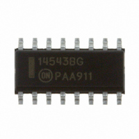
Manufacturer Part Number
MC14543BDG
Description
IC LATCH/DECODER/DRIVER 16SOIC
Manufacturer
ON Semiconductor
Datasheet
1.MC14543BDG.pdf
(8 pages)
Specifications of MC14543BDG
Display Type
LCD
Configuration
7 Segment
Interface
BCD
Current - Supply
10µA
Voltage - Supply
3 V ~ 18 V
Operating Temperature
-55°C ~ 125°C
Mounting Type
Surface Mount
Package / Case
16-SOIC (3.9mm Width)
Product
Decoder / Demultiplexer
Logic Family
MC14
Supply Voltage (max)
18 V
Supply Voltage (min)
3 V
Maximum Operating Temperature
+ 125 C
Minimum Operating Temperature
- 55 C
Mounting Style
SMD/SMT
Power Dissipation
500 mW
Logical Function
Latch/Decoder/Driver
Number Of Elements
1
Polarity
Non-Inverting
Number Of Inputs
4
Number Of Outputs
7
Propagation Delay Time
1650ns
Package Type
SOIC
High Level Output Current
-4.2mA
Low Level Output Current
4.2mA
Operating Supply Voltage (typ)
3.3/5/9/12/15V
Operating Supply Voltage (max)
18V
Operating Supply Voltage (min)
3V
Operating Temp Range
-55C to 125C
Operating Temperature Classification
Military
Mounting
Surface Mount
Pin Count
16
Quiescent Current
20uA
Technology
CMOS
Lead Free Status / RoHS Status
Lead free / RoHS Compliant
Digits Or Characters
-
Lead Free Status / Rohs Status
Lead free / RoHS Compliant
Other names
MC14543BDGOS


−T−
16
1
SEATING
PLANE
H
16
1
−A−
G
G
D
0.25 (0.010)
−A−
16 PL
F
D
9
8
16 PL
0.25 (0.010)
M
B
S
T
9
8
K
B
K
C
M
−B−
S
−T−
T
A
A
C
S
P
SEATING
PLANE
PACKAGE DIMENSIONS
M
8 PL
http://onsemi.com
0.25 (0.010)
CASE 751B−05
J
CASE 648−08
MC14543B
M
SOIC−16
PDIP−16
ISSUE T
ISSUE J
7
M
L
R
B
X 45
S
_
M
J
F
NOTES:
1. DIMENSIONING AND TOLERANCING PER
2. CONTROLLING DIMENSION: INCH.
3. DIMENSION L TO CENTER OF LEADS
4. DIMENSION B DOES NOT INCLUDE
5. ROUNDED CORNERS OPTIONAL.
ANSI Y14.5M, 1982.
WHEN FORMED PARALLEL.
MOLD FLASH.
DIM
G
M
A
B
C
D
F
H
J
K
L
S
NOTES:
1. DIMENSIONING AND TOLERANCING PER ANSI
2. CONTROLLING DIMENSION: MILLIMETER.
3. DIMENSIONS A AND B DO NOT INCLUDE
4. MAXIMUM MOLD PROTRUSION 0.15 (0.006)
5. DIMENSION D DOES NOT INCLUDE DAMBAR
0.740
0.250
0.145
0.015
0.040
0.008
0.295
0.020
0.110
MIN
0.100 BSC
0.050 BSC
Y14.5M, 1982.
MOLD PROTRUSION.
PER SIDE.
PROTRUSION. ALLOWABLE DAMBAR
PROTRUSION SHALL BE 0.127 (0.005) TOTAL
IN EXCESS OF THE D DIMENSION AT
MAXIMUM MATERIAL CONDITION.
0
DIM
INCHES
A
B
C
D
G
K
M
R
F
J
P
_
0.770
0.270
0.175
0.021
0.015
0.130
0.305
0.040
MILLIMETERS
MAX
MIN
0.70
9.80
3.80
1.35
0.35
0.40
0.19
0.10
5.80
0.25
10
1.27 BSC
0
_
_
10.00
18.80
MAX
MILLIMETERS
4.00
1.75
0.49
1.25
0.25
0.25
6.20
0.50
6.35
3.69
0.39
1.02
0.21
2.80
7.50
0.51
MIN
7
2.54 BSC
1.27 BSC
0
_
_
0.150
0.054
0.014
0.016
0.008
0.004
0.229
0.010
0.386
MIN
19.55
MAX
0.050 BSC
6.85
4.44
0.53
1.77
0.38
3.30
7.74
1.01
0
10
INCHES
_
_
0.393
0.157
0.068
0.019
0.049
0.009
0.009
0.244
0.019
MAX
7
_
Related parts for MC14543BDG
Image
Part Number
Description
Manufacturer
Datasheet
Request
R

Part Number:
Description:
CONTACTOR, 1NO, 110VAC, 14A, DIN RAIL
Manufacturer:
IMO PRECISION CONTROLS
Datasheet:
Part Number:
Description:
CONTACTOR, 1NO, 230VAC, 14A, DIN RAIL
Manufacturer:
IMO PRECISION CONTROLS
Datasheet:
Part Number:
Description:
CONTACTOR, 1NO, 24VAC, 14A, DIN RAIL
Manufacturer:
IMO PRECISION CONTROLS
Datasheet:

Part Number:
Description:
ON Semiconductor [VOLTAGE REGULATOR]
Manufacturer:
ON Semiconductor
Datasheet:
Part Number:
Description:
357-036-542-201 CARDEDGE 36POS DL .156 BLK LOPRO
Manufacturer:
ON Semiconductor
Datasheet:
Part Number:
Description:
357-036-542-201 CARDEDGE 36POS DL .156 BLK LOPRO
Manufacturer:
ON Semiconductor
Datasheet:
Part Number:
Description:
357-036-542-201 CARDEDGE 36POS DL .156 BLK LOPRO
Manufacturer:
ON Semiconductor
Datasheet:
Part Number:
Description:
357-036-542-201 CARDEDGE 36POS DL .156 BLK LOPRO
Manufacturer:
ON Semiconductor
Datasheet:
Part Number:
Description:
357-036-542-201 CARDEDGE 36POS DL .156 BLK LOPRO
Manufacturer:
ON Semiconductor
Datasheet:
Part Number:
Description:
357-036-542-201 CARDEDGE 36POS DL .156 BLK LOPRO
Manufacturer:
ON Semiconductor
Datasheet:
Part Number:
Description:
357-036-542-201 CARDEDGE 36POS DL .156 BLK LOPRO
Manufacturer:
ON Semiconductor
Datasheet:
Part Number:
Description:
357-036-542-201 CARDEDGE 36POS DL .156 BLK LOPRO
Manufacturer:
ON Semiconductor
Datasheet:
Part Number:
Description:
357-036-542-201 CARDEDGE 36POS DL .156 BLK LOPRO
Manufacturer:
ON Semiconductor
Datasheet:
Part Number:
Description:
357-036-542-201 CARDEDGE 36POS DL .156 BLK LOPRO
Manufacturer:
ON Semiconductor
Datasheet: