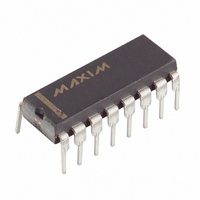
MAX6958BAPE+ Maxim Integrated Products, MAX6958BAPE+ Datasheet - Page 15

MAX6958BAPE+
Manufacturer Part Number
MAX6958BAPE+
Description
IC DRVR DSPL LED 16-DIP
Manufacturer
Maxim Integrated Products
Datasheet
1.MAX6958AAEE.pdf
(19 pages)
Specifications of MAX6958BAPE+
Display Type
LED
Configuration
7 Segment + 2 Annunciators
Interface
SMBus (2-Wire/I²C)
Digits Or Characters
4 Digits
Current - Supply
5.9mA
Voltage - Supply
3 V ~ 5.5 V
Operating Temperature
-40°C ~ 125°C
Mounting Type
Through Hole
Package / Case
16-DIP (0.300", 7.62mm)
Number Of Digits
4
Number Of Segments
36
Low Level Output Current
275 mA
High Level Output Current
30 mA
Operating Supply Voltage
3 V to 5.5 V
Maximum Supply Current
6.7 mA
Maximum Power Dissipation
842 mW
Maximum Operating Temperature
+ 125 C
Mounting Style
Through Hole
Minimum Operating Temperature
- 40 C
Lead Free Status / RoHS Status
Lead free / RoHS Compliant
Figure 14. Keyscan Timing Diagram
pullup resistor from IRQ/SEG9 to a voltage no greater
than 5.5V when configuring IRQ/SEG9 as an interrupt
or logic output.
INPUT1 and INPUT2 can be individually configured as
either general-purpose logic inputs or as keyscan
inputs. In either mode, the input structure is the same—
CMOS logic inputs with internal pullup resistors. The
Table 16. Port Configuration Register Format
This is the bit assignment:
Read GPIO register
Write GPIO register
Here are the IRQ/SEG9 allocation options, determined by the settings of D7, D6, D5:
IRQ/SEG9 is logic 0 output
IRQ/SEG9 is logic 1 output
IRQ/SEG9 is active-low
IRQ
IRQ/SEG9 is active-high
IRQ
IRQ/SEG9 is segment
driver
DIG0/SEG0
DIG1/SEG1
DIG2/SEG2
DIG3/SEG3
INPUT1 Key0
INPUT2
FIRST TEST OF KEYS
9-Segment LED Display Drivers with Keyscan
Key4 Key5 Key6 Key7
1.28ms MULTIPLEX
A
Key1 Key2 Key3
MODE
CYCLE 1
5µs TO 315µs DIGIT PERIOD
B
1.28ms MULTIPLEX
______________________________________________________________________________________
CYCLE 2
THE FIRST HALF OF A 41ms KEYSCAN CYCLE
ADDRESS
2-Wire Interfaced, 3V to 5.5V, 4-Digit,
1.28ms MULTIPLEX
CODE
(HEX)
0x06
0x06
0x06
0x06
0x06
0x06
0x06
CYCLE 3
1.28ms MULTIPLEX
Read back
IRQ/SEG9
configuration
Configure
IRQ/SEG9
output
D7 D6 D5
0
0
0
0
1
CYCLE 4
0
0
1
1
X
X
0
1
0
1
1.28ms MULTIPLEX
Read back
INPUT 2
configuration
Configure
INPUT 2:
0 = logic input
1 = keyscan
CYCLE 15
SECOND TEST OF KEYS
D4
X
X
X
X
X
t
DEBOUNCE
C
Key0 Key1 Key2 Key3
Key4 Key5 Key6 Key7
1.28ms MULTIPLEX
pullups are always enabled, even in shutdown. Ensure
these inputs are either close to V+ or open circuit for
minimum shutdown supply current. If both INPUT1 and
INPUT2 are assigned to keyscan, then eight keys can
be debounced. If only INPUT1 or INPUT2 is assigned
to keyscan, then only four keys can be debounced.
CYCLE 16
Read back
INPUT 1
configuration
Configure
INPUT 1:
0 = logic input
1 = keyscan
REGISTER DATA
D
INTERRUPT ASSERTED IF REQUIRED
KEY DEBOUNCED REGISTER UPDATED
D3
1.28ms MULTIPLEX
X
X
X
X
X
CYCLE 1
INPUT2
logic level
THE SECOND HALF OF A 41ms KEYSCAN CYCLE
1.28ms MULTIPLEX
CYCLE 2
D2
X
X
X
X
X
X
INPUT1
logic level
1.28ms MULTIPLEX
CYCLE 15
D1
X
X
X
X
X
X
START OF NEXT KEYSCAN CYCLE
1.28ms MULTIPLEX
IRQ status
( 1 = i nter rup t)
CYCLE 16
D0
X
X
X
X
X
X
A
E
15


