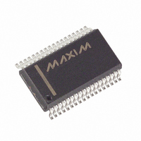
MAX5952AEAX+ Maxim Integrated Products, MAX5952AEAX+ Datasheet - Page 12

MAX5952AEAX+
Manufacturer Part Number
MAX5952AEAX+
Description
IC PSE CNTRLR FOR POE 36-SSOP
Manufacturer
Maxim Integrated Products
Type
Power Over Ethernet Controller (PoE)r
Datasheet
1.MAX5952AUAX.pdf
(50 pages)
Specifications of MAX5952AEAX+
Applications
Remote Peripherals (Industrial Controls, Cameras, Data Access)
Internal Switch(s)
No
Operating Temperature
-40°C ~ 85°C
Mounting Type
Surface Mount
Package / Case
36-BSOP (0.300", 7.5mm Width)
Product
Controllers & Switches
Supply Voltage (max)
5.5 V
Supply Voltage (min)
1.71 V
Power Dissipation
941 mW
Operating Temperature Range
- 40 C to + 85 C
Mounting Style
SMD/SMT
Supply Current
4.8 mA
Input Voltage
60V
Digital Ic Case Style
SSOP
No. Of Pins
36
Uvlo
28.5V
Frequency
400kHz
Interface
I2C
Termination Type
SMD
Rohs Compliant
Yes
Filter Terminals
SMD
Controller Type
Power Over Ethernet PD
Lead Free Status / RoHS Status
Lead free / RoHS Compliant
High-Power, Quad, PSE Controller
for Power-Over-Ethernet
(V
T
12
A
EE
= +25°C, all registers = default setting, unless otherwise noted.)
PIN
1
2
3
4
5
6
= -48V, V
______________________________________________________________________________________
V
0V
0A
DETECTION WITH INVALID PD (OPEN CIRCUIT,
EE
USING TYPICAL OPERATING CIRCUIT 2)
MIDSPAN
SDAOUT
DD
RESET
NAME
SDAIN
SCL
INT
= +3.3V, V
40ms/div
Hardware Reset. Pull RESET low for at least 300µs to reset the device. All internal registers reset to their
default value. The address (A0–A3), and AUTO and MIDSPAN input-logic levels latch on during low-to-
high transition of RESET. RESET is internally pulled up to V
Midspan Mode Input. An internal 50kΩ pulldown resistor to DGND sets the default mode to end-point PSE
operation (power-over-signal pairs). Pull MIDSPAN to V
latches after the IC is powered up or reset (see the PD Detection section).
Open-Drain Interrupt Output. INT goes low whenever a fault condition exists. Reset the fault condition
using software or by pulling RESET low (see the Interrupt section for more information about interrupt
management).
Serial Interface Clock Line Input
Serial Output Data Line. Connect the data line optocoupler input to SDAOUT (see the Typical Operating
Circuits). Connect SDAOUT to SDAIN if using a 2-wire, I
Serial Interface Input Data Line. Connect the data line optocoupler output to SDAIN (see the Typical
Operating Circuits). Connect SDAIN to SDAOUT if using a 2-wire, I
AUTO
= V
AGND
MAX5952 toc28
= V
(AGND - V
5V/div
I
1mA/div
V
10V/div
OUT
GATE_
DGND
Typical Operating Characteristics (continued)
OUT
= 0V, RESET = SHD_ = unconnected, R
)
FUNCTION
DIG
2
C-compatible system.
STARTUP WITH DIFFERENT PD CLASSES
DD
to set midspan operation. The MIDSPAN value
with a 50kΩ resistor.
2
SENSE
C-compatible system.
40ms/div
= 0.5Ω, IVEE = 00, ICUT = 000,
CLASS 5
CLASS 4
CLASS 3
CLASS 2
CLASS 1
Pin Description
MAX5952 toc29
(AGND - V
5V/div
I
20mA/div
OUT
OUT
)


