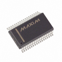
MAX5965AUAX+ Maxim Integrated Products, MAX5965AUAX+ Datasheet - Page 22

MAX5965AUAX+
Manufacturer Part Number
MAX5965AUAX+
Description
IC PSE CTRLR FOR POE 36SSOP
Manufacturer
Maxim Integrated Products
Type
Power Over Ethernet Controller (PoE)r
Datasheet
1.MAX5965AUAXT.pdf
(53 pages)
Specifications of MAX5965AUAX+
Applications
IP Phones, Power over LAN, Network Routers and Switches
Internal Switch(s)
No
Voltage - Supply
2.4 V ~ 3.6 V
Operating Temperature
0°C ~ 85°C
Mounting Type
Surface Mount
Package / Case
36-BSOP (0.300", 7.5mm Width)
Lead Free Status / RoHS Status
Lead free / RoHS Compliant
High-Power, Quad, Monolithic, PSE Controllers
for Power over Ethernet
V
ranges from +3.0V to +5.5V and determines the logic
thresholds for the CMOS connections (SDAIN, SDAOUT,
SCL, AUTO, SHD_, A_). This voltage range enables the
MAX5965A/MAX5965B to interface with a nonisolated
low-voltage microcontroller. The MAX5965A/MAX5965B
check the digital supply for compatibility with the internal
logic. The MAX5965A/MAX5965B also feature a V
undervoltage lockout (V
condition keeps the MAX5965A/MAX5965B in reset and
the ports shut off. Bit 0 in the supply event register shows
the status of V
ered. All logic inputs and outputs reference to DGND.
For AC-disconnected detection, DGND and AGND must
be connected together externally. Connect DGND to
AGND at a single point in the system as close as possi-
ble to the MAX5965A/MAX5965B.
SHD_ shuts down the respective ports without using the
serial interface. Hardware shutdown offers an emer-
gency turn-off feature that allows a fast disconnect of
the power supply from the port. Pull SHD_ low to
remove power. SHD_ also resets the corresponding
events and status register bits.
The MAX5965A/MAX5965B contain an open-drain logic
output (INT) that goes low when an interrupt condition
exists. R00h and R01h (Tables 6 and 7) contain the defin-
itions of the interrupt registers. The mask register R01h
determines events that trigger an interrupt. As a response
to an interrupt, the controller reads the status of the event
register to determine the cause of the interrupt and takes
subsequent actions. Each interrupt event register also
contains a Clear on Read (CoR) register. Reading
through the CoR register address clears the interrupt. INT
remains low when reading the interrupt through the read-
only addresses. For example, to clear a startup fault on
the port 4 read address 09h (see Table 11). Use the glob-
al pushbutton bit in register 1Ah (bit 7, Table 23) to clear
interrupts, or use a software or hardware reset.
The MAX5965A/MAX5965B contain several undervoltage
and overvoltage protection features. Table 12 in the
Register Map and Description section shows a detailed
list of the undervoltage and overvoltage protection fea-
tures. An internal V
cuit keeps the MOSFET off and the MAX5965A/
MAX5965B in reset until V
more than 3ms. An internal V
cuit shuts down the ports when (V
22
DD
______________________________________________________________________________________
supplies power for the internal logic circuitry. V
DDUVLO
EE
undervoltage lockout (V
(Table 12) after V
DDUVLO
Overvoltage Protection
AGND
EE
Hardware Shutdown
overvoltage (V
) of +2.0V. A V
Undervoltage and
- V
AGND
EE
exceeds 29V for
Digital Logic
- V
DD
EE
EEUVLO
Interrupt
has recov-
EE_OV
) exceeds
DDUVLO
) cir-
) cir-
DD
DD
60V. The digital supply also contains an undervoltage
lockout (V
ture three other undervoltage and overvoltage interrupts:
V
interrupt (V
(V
(Table 12), but the MAX5965A/MAX5965B does not shut
down the ports with V
Setting R13h[DCD_EN_] bits high enables DC load moni-
toring during a normal powered state. If V
across R
V
and asserts the LD_DISC_ bit of the corresponding port.
The MAX5965A/MAX5965B feature AC load disconnect
monitoring. Connect an external sine wave to OSC. The
oscillator requirements are:
1) V
2) Positive peak voltage > +2.2V
3) Frequency > 60Hz
A 100Hz ±10%, 2V
+2.3V typical) is recommended.
The MAX5965A/MAX5965B buffer and amplify three
times the external oscillator signal and sends the signal
to DET_, where the sine wave is AC-coupled to the out-
put. The MAX5965A/MAX5965B sense the presence of
the load by monitoring the amplitude of the AC current
returned to DET_ (see the Functional Diagram ).
Setting R13h[ACD_EN_] bits high enable AC load dis-
connect monitoring during a normal powered state. If
the AC current peak at the DET_ input falls below I
for more than t
asserts the LD_DISC_ bit of the corresponding port.
I
An internal comparator checks for a proper amplitude of
the oscillator input. If the positive peak of the input sinu-
soid falls below a safety value of 2V (typ), OSC_FAIL
sets and the port shuts down. Power cannot be applied
to the ports when ACD_EN_ is set high and OSC_FAIL
is set high. Leave OSC unconnected or connect it to
DGND when not using AC-disconnect detection.
If the MAX5965A/MAX5965B die temperature reaches
+150°C, an overtemperature fault generates and the
MAX5965A/MAX5965B shut down. The MOSFETs turn off.
The die temperature of the MAX5965A/MAX5965B must
cool down below +130°C to remove the overtemperature
fault condition. After a thermal shutdown, the part is reset.
ACTH
EE
DCTH
DDOV
undervoltage interrupt (V
P-P
is programmable using R23h[2:0].
, for more than t
). A fault latches into the supply events register
S
x Frequency = 200V
DDUVLO
) falls below the DC load disconnect threshold,
DDUV
DISC
). The MAX5965A/MAX5965B also fea-
), and V
P-P
EEUV
, the device turns off power and
DC Disconnect Monitoring
AC Disconnect Monitoring
±5%, with +1.3V offset (V
DISC
(MAX5965A/MAX5965B)
, V
, the device turns off power
DDUV
DD
P-P
EEUV
Thermal Shutdown
overvoltage interrupt
x Hz ±15%
, or V
), V
DDOV
DD
RS
undervoltage
.
(the voltage
PEAK
ACTH
=


