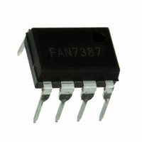
FAN7387N Fairchild Semiconductor, FAN7387N Datasheet

FAN7387N
Specifications of FAN7387N
Related parts for FAN7387N
FAN7387N Summary of contents
Page 1
... Ballast for Fluorescent Lamp Ordering Information Part Number Package (1) FAN7387M 8-SOP (1) FAN7387MX FAN7387N 8-DIP For Fairchild’s definition of “green” Eco Status, please visit: http://www.fairchildsemi.com/company/green/rohs_green.html. Note: 1. These device passed wave soldering test by JESD22A-111. © 2008 Fairchild Semiconductor Corporation FAN7387 • 1.0.2 Description ...
Page 2
... Typical Applications Diagrams VDD RT1 RDT Q1 Q2 Frequency Shutdown Control GND * Note: This capacitor, Cb, is for system stability and must use at least 470nF. Figure 1. Figure 2. © 2008 Fairchild Semiconductor Corporation FAN7387 • 1.0 RCT VDD GND Cb* RT2 Typical Application Circuit for SMPS (Self Oscillation Method) ...
Page 3
... Typical Application Diagrams Figure 3. Figure 4. © 2008 Fairchild Semiconductor Corporation FAN7387 • 1.0.2 (Continued) Typical Application Circuit for Full-Bridge Converter Typical Application Circuit for Fluorescent Lamp Ballast 3 www.fairchildsemi.com ...
Page 4
... Supply Voltage. 3 DT/SD Dead-time control and shutdown (active LOW). 4 GND Signal Ground Low-Side Output High-Side floating supply return High-Side output High-Side floating supply. © 2008 Fairchild Semiconductor Corporation FAN7387 • 1.0.2 Figure 5. Functional Block Diagram FAN7387 YWW ( YWW : Work Week Code ...
Page 5
... Logic “1” Input Voltage of RCT IH V Logic “0” Input Voltage of RCT IL R Timing Resistor Value of RCT T C Timing Capacitor Value of RCT T T Ambient Temperature A © 2008 Fairchild Semiconductor Corporation FAN7387 • 1.0.2 =25°C unless otherwise specified. A Parameter (2) 8-DIP 8-SOP 8-DIP 8-SOP Parameter (3 Min. ...
Page 6
... I Output Low, Short-Circuit Pulse Current O- Allowable Negative Signal (V ) Propagation to HO RCT Note: 3. These parameters, although guaranteed, is not 100% tested in production. © 2008 Fairchild Semiconductor Corporation FAN7387 • 1.0.2 =50k and C =330pF and T =25°C, unless otherwise specified Test Conditions ) DD V Increasing ...
Page 7
... Turn-Off Falling Time F Protection Characteristics /SD+ Shutdown “1” Input Voltage /SD- Shutdown “0” Input Voltage I Shutdown Current SD t Shutdown Propagation Delay SD © 2008 Fairchild Semiconductor Corporation FAN7387 • 1.0.2 (Continued) =50k and C =330pF and T =25°C, unless otherwise specified Test Conditions V =V =14V, V ...
Page 8
... Switching Definitions μ Figure 7. Test Circuit for Self-Oscillation Method Figure 9. Shutdown Delay Definition Figure 11. Basic Operation Waveforms of Forced-oscillation Method Using External Signal © 2008 Fairchild Semiconductor Corporation FAN7387 • 1.0.2 μ Figure 8. Basic Operating Waveforms of Self-Oscillation μ Figure 10. Test Circuit for Forced-Oscillation Method ...
Page 9
... Figure 14. V UVLO- vs. Temperature DD 10.0 9.6 9.2 8.8 8.4 8.0 7.6 7.2 -40 - Temperature [°C] Figure 16. V UVLO- vs. Temperature BS © 2008 Fairchild Semiconductor Corporation FAN7387 • 1.0.2 12.5 12.0 11.5 11.0 10.5 10.0 9.5 - 100 120 Figure 13. V 10.0 9.6 9.2 8.8 8.4 8 ...
Page 10
... Temperature [°C] Figure 20. I vs. Temperature SD 3.0 2.5 2.0 1.5 1.0 -40 - Temperature [°C] Figure 22 vs. Temperature SD © 2008 Fairchild Semiconductor Corporation FAN7387 • 1.0.2 (Continued) 500 400 300 200 100 100 120 -40 3.0 2.5 2.0 1.5 1.0 0.5 0.0 - 100 ...
Page 11
... Temperature [°C] Figure 24. Operating Frequency 2 vs. Temperature -40 - Temperature [°C] Figure 26. Dead-Time Mismatch vs. Temperature -40 - Temperature [°C] Figure 28. Low-Side Duty Ratio vs. Temperature © 2008 Fairchild Semiconductor Corporation FAN7387 • 1.0.2 (Continued) 500 475 450 425 400 375 350 325 300 - 100 120 100 120 -40 Figure 27 ...
Page 12
... From equation possible to calculate discharging time, t, from substituting 1/4 VDD. Figure 31. Typical Waveforms of RCT,LO and HO © 2008 Fairchild Semiconductor Corporation FAN7387 • 1.0 The running frequency determined by 1/T and is approximately given as: +, the UV f running Where the discharging time of the RCT voltage and ...
Page 13
... Package drawings are provided as a service to customers considering Fairchild components. Drawings may change in any manner without notice. Please note the revision and/or date on the drawing and contact a Fairchild Semiconductor representative to verify or obtain the most recent revision. Package specifications do not expand the terms of Fairchild’s worldwide terms and conditions, specifically the warranty therein, which covers Fairchild products. Always visit Fairchild Semiconductor’ ...
Page 14
... Package drawings are provided as a service to customers considering Fairchild components. Drawings may change in any manner without notice. Please note the revision and/or date on the drawing and contact a Fairchild Semiconductor representative to verify or obtain the most recent revision. Package specifications do not expand the terms of Fairchild’s worldwide terms and conditions, specifically the warranty therein, which covers Fairchild products. Always visit Fairchild Semiconductor’ ...
Page 15
... Fairchild Semiconductor Corporation FAN7387 • 1.0.2 15 www.fairchildsemi.com ...


