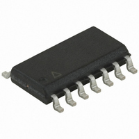
U2044B-MFPG3Y Atmel, U2044B-MFPG3Y Datasheet - Page 4

U2044B-MFPG3Y
Manufacturer Part Number
U2044B-MFPG3Y
Description
IC FLASH CONTROL 10W DUAL 14SOIC
Manufacturer
Atmel
Type
Automotive, Flasherr
Datasheet
1.U2044B-MFPG3Y.pdf
(9 pages)
Specifications of U2044B-MFPG3Y
Current - Supply
10µA
Current - Output
100µA
Voltage - Supply
8 V ~ 18 V
Operating Temperature
-40°C ~ 100°C
Package / Case
14-SOIC (3.9mm Width), 14-SOL
Mounting Style
SMD/SMT
Lead Free Status / RoHS Status
Lead free / RoHS Compliant
Frequency
-
Lead Free Status / Rohs Status
Lead free / RoHS Compliant
Available stocks
Company
Part Number
Manufacturer
Quantity
Price
Company:
Part Number:
U2044B-MFPG3Y
Manufacturer:
ATMEL
Quantity:
412
Part Number:
U2044B-MFPG3Y
Manufacturer:
TFK
Quantity:
20 000
Company:
Part Number:
U2044B-MFPG3Y-66
Manufacturer:
ATMEL
Quantity:
25 221
Part Number:
U2044B-MFPG3Y-66
Manufacturer:
ATMEL/爱特梅尔
Quantity:
20 000
3. Functional Description
3.1
3.2
3.3
3.4
3.5
4
Oscillator (Pin 1 and 14)
Start Input Right and Left (Pin 2 and 3)
Start Input Hazard Warning (Pin 4)
Supply Voltage Sense (Pin 5)
Control Input Relay 1 and 2 (Pin 6 and 7)
U2044B
Flashing frequency, f
page
where
In the case of a lamp outage, the oscillator frequency is switched to the lamp outage frequency
f
Duty cycle in normal flashing mode:
Duty cycle in lamp outage mode:
Flashing is disabled as long as the input comparator is tied to GND (pull-down resistor R
The high-side flasher switch left or right changes the comparator status and enables the output
stage at pin 11 or pin 13. R
With an open flasher switch the current consumption is only I < 10 µA. The IC is kept in stand-by
mode until there is a voltage drop of V
Direction mode can only be activated when the ignition switch is in the ON-position as shown in
Figure 1-1 on page
In contrast to the direction switches, the hazard input is a low-side type. The pull-up resistor R
provides the off-state. R
vated independent of the ignition switch position.
This pin supplies the lamp outage comparator at pin 8 and is externally connected to the battery
(Kl 30).
The feedback detects the bright phase and the dark phase and enables the oscillator.
f
2
1
with f
------------------------------------ - Hz
R
2):
1
2
C
1
2.2
1
1.5
f
1
.
2.
1
C
R
, is determined by the R
1
1
3
is a protection resistor for the input stage. Hazard warning can be acti-
= 6.8 k to 180 k
47 µF
6
and R
4
are protection resistors for the input stage.
50%
40% (bright phase)
6.9V at the pull-down resistor.
1
C
1
components as follows (see
4721C–AUTO–02/08
Figure 1-1 on
7
or R
5
10
).


