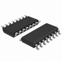
UBA2014T/N1,518 NXP Semiconductors, UBA2014T/N1,518 Datasheet - Page 6

UBA2014T/N1,518
Manufacturer Part Number
UBA2014T/N1,518
Description
IC CNTL BALLAST 600V 16-SOIC
Manufacturer
NXP Semiconductors
Type
Ballast Controllerr
Datasheet
1.UBA2014TN1518.pdf
(19 pages)
Specifications of UBA2014T/N1,518
Package / Case
16-SOIC (3.9mm Width)
Frequency
40.5 ~ 100 kHz
Current - Supply
1.5mA
Current - Output
330mA
Voltage - Supply
9.1 V ~ 13 V
Operating Temperature
-25°C ~ 80°C
Driver Type
CCFL, HFTL Drivers
Maximum Operating Temperature
+ 80 C
Mounting Style
SMD/SMT
Minimum Operating Temperature
- 25 C
Lead Free Status / RoHS Status
Lead free / RoHS Compliant
Lead Free Status / RoHS Status
Lead free / RoHS Compliant, Lead free / RoHS Compliant
Other names
568-3322-2
935270228518
UBA2014TD-T
935270228518
UBA2014TD-T
Available stocks
Company
Part Number
Manufacturer
Quantity
Price
Part Number:
UBA2014T/N1,518
Manufacturer:
NXP/恩智浦
Quantity:
20 000
NXP Semiconductors
UBA2014_4
Product data sheet
8.8.1 During ignition state
8.8.2 During burn state
8.5 Preheat state
8.6 Ignition state
8.7 Burn state
8.8 Lamp failure mode
After starting at f
across sense resistor R14 reaches the internally fixed preheat voltage level (pin PCS). At
crossing the preheat voltage level, the output current of the
Preheat Current Sensor (PCS) circuit discharges the capacitor C
frequency. The preheat time begins at the moment that the circuit starts oscillating. During
the preheat time the Average Current Sensor (ACS) circuit is disabled. An internal filter of
30 ns is included at pin PCS to increase the noise immunity.
After the preheat time the ignition state is entered and the frequency will sweep down due
to charging of the capacitor at pin CSW with an internally fixed current; see
During this continuous decrease in frequency, the circuit approaches the resonant
frequency of the load. This will cause a high voltage across the load, which normally
ignites the lamp. The ignition voltage of a lamp is designed above the V
lamp voltage exceeds the V
If the lamp voltage does not exceed the V
continue to increase until the clamp level at pin CSW is reached; see
consequence the frequency will decrease until the minimum frequency is reached.
When the frequency reaches its minimum level it is assumed that the lamp has ignited and
the circuit will enter the burn state. The ACS circuit will be enabled. As soon as the
averaged voltage across sense resistor R14, measured at pin CSN, reaches the reference
level at pin CSP, the average current sensor circuit will take over the control of the lamp
current. The average current through R14 is transferred to a voltage at the voltage
controlled oscillator and regulates the frequency and, as a result, the lamp current.
If the lamp does not ignite, the voltage level increases. When the lamp voltage exceeds
the V
When the V
pin LVS is above the V
oscillating and is forced into the Power-down mode. The circuit will be reset only when the
supply voltage is powered down.
If the lamp fails during normal operation, the voltage across the lamp will increase and the
lamp voltage will exceed the V
is started. If the lamp voltage increases further it will reach the V
the circuit to reenter the ignition state and results in an attempt to re-ignite the lamp. If
during restart the lamp still fails, the voltage remains high until the end of the ignition time.
At the end of the ignition time the circuit stops oscillating and the circuit will enter the
Power-down mode.
lamp(max)
lamp(fail)
level, the voltage will be regulated at the V
max
level is crossed the ignition timer has already started. If the voltage at
, the frequency decreases until the momentary value of the voltage
Rev. 04 — 16 October 2008
lamp(fail)
lamp(fail)
lamp(fail)
level at the end of the ignition time the circuit stops
level the ignition timer is started.
level; see
lamp(max)
600 V driver IV for HF fluorescent lamps
Figure
level the voltage at pin CSW will
7. At that moment the ignition timer
lamp(max)
lamp(max)
CSW
level; see
, thus raising the
Figure
UBA2014
lamp(fail)
© NXP B.V. 2008. All rights reserved.
level. This forces
Figure
Figure
5. As a
level. If the
6.
5.
6 of 19


