IRS2106PBF International Rectifier, IRS2106PBF Datasheet - Page 3
IRS2106PBF
Manufacturer Part Number
IRS2106PBF
Description
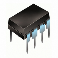
IC DRIVER HIGH/LOW SIDE 8-DIP
Manufacturer
International Rectifier
Datasheet
1.IRS2106SPBF.pdf
(25 pages)
Specifications of IRS2106PBF
Configuration
High and Low Side
Input Type
Non-Inverting
Delay Time
220ns
Current - Peak
290mA
Number Of Configurations
1
Number Of Outputs
2
High Side Voltage - Max (bootstrap)
600V
Voltage - Supply
10 V ~ 20 V
Operating Temperature
-40°C ~ 125°C
Mounting Type
Through Hole
Package / Case
8-DIP (0.300", 7.62mm)
Lead Free Status / RoHS Status
Lead free / RoHS Compliant


Recommended Operating Conditions
The input/output logic timing diagram is shown in Fig. 1. For proper operation the device should be used within the
recommended conditions. The V
Note 1: Logic operational for V
DT97-3 for more details).
www.irf.com
Dynamic Electrical Characteristics
V
Symbol
Symbol
BIAS
V
V
V
V
MT
t on
t off
V
VB
V
T
t r
t f
HO
CC
LO
SS
IN
(V
S
A
CC
, V
BS
Turn-on propagation delay
Turn-off propagation delay
Delay matching, HS & LS turn-on/off
Turn-on rise time
Turn-off fall time
High-side floating supply absolute voltage
High-side floating supply offset voltage
High-side floating output voltage
Low-side and logic fixed supply voltage
Low-side output voltage
Logic input voltage
Logic ground (IRS21064 only)
Ambient temperature
) = 15 V, V
SS
Definition
S
= COM, C
S
of -5 V to +600 V. Logic state held for V
and V
Definition
SS
L
= 1000 pF, T
offset rating are tested with all supplies biased at a 15 V differential.
A
= 25 °C.
IRS2106/IRS21064(S)PbF
Min.
—
—
—
—
—
S
of -5 V to -V
Typ.
220
200
100
35
0
V
Max. Units Test Conditions
Min.
Note 1
S
300
280
220
V
-40
30
80
V
10
-5
BS
0
SS
+ 10
S
. (Please refer to the Design Tip
ns
V
Max.
S
V
V
125
600
V
20
V
5
+ 20
CC
CC
B
S
= 0 V or 600 V
V
V
S
S
= 0 V
= 0 V
Units
°
C
V
3
Related parts for IRS2106PBF
Image
Part Number
Description
Manufacturer
Datasheet
Request
R

Part Number:
Description:
HIGH AND LOW SIDE DRIVER
Manufacturer:
IRF [International Rectifier]
Datasheet:

Part Number:
Description:
(IRS2106(4)D(S)PbF) High and Low Side Driver
Manufacturer:
International Rectifier
Datasheet:

Part Number:
Description:
SCHOTTKY RECTIFIER
Manufacturer:
International Rectifier Corp.
Datasheet:
Part Number:
Description:
SCHOTTKY RECTIFIER
Manufacturer:
International Rectifier Corp.
Datasheet:
Part Number:
Description:
SCHOTTKY RECTIFIER
Manufacturer:
International Rectifier Corp.
Datasheet:
Part Number:
Description:
SCHOTTKY RECTIFIER
Manufacturer:
International Rectifier Corp.
Datasheet:
Part Number:
Description:
SCHOTTKY RECTIFIER
Manufacturer:
International Rectifier Corp.
Datasheet:
Part Number:
Description:
SCHOTTKY RECTIFIER
Manufacturer:
International Rectifier Corp.
Datasheet:
Part Number:
Description:
SCHOTTKY RECTIFIER
Manufacturer:
International Rectifier Corp.
Datasheet:
Part Number:
Description:
SCHOTTKY RECTIFIER
Manufacturer:
International Rectifier Corp.
Datasheet:
Part Number:
Description:
SCHOTTKY RECTIFIER
Manufacturer:
International Rectifier Corp.
Datasheet:
Part Number:
Description:
SCHOTTKY RECTIFIER
Manufacturer:
International Rectifier Corp.
Datasheet:
Part Number:
Description:
SCHOTTKY RECTIFIER
Manufacturer:
International Rectifier Corp.
Datasheet:
Part Number:
Description:
SCHOTTKY RECTIFIER
Manufacturer:
International Rectifier Corp.
Datasheet:
Part Number:
Description:
SCHOTTKY RECTIFIER
Manufacturer:
International Rectifier Corp.
Datasheet: