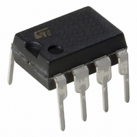
L6384 STMicroelectronics, L6384 Datasheet - Page 4

L6384
Manufacturer Part Number
L6384
Description
IC DRVR HALF BRIDGE HV 8MINIDIP
Manufacturer
STMicroelectronics
Type
Driverr
Specifications of L6384
Configuration
Half Bridge
Input Type
Inverting
Current - Peak
400mA
Number Of Configurations
1
Number Of Outputs
2
High Side Voltage - Max (bootstrap)
600V
Voltage - Supply
8 V ~ 16.6 V
Operating Temperature
-45°C ~ 125°C
Mounting Type
Through Hole
Package / Case
8-DIP (0.300", 7.62mm)
Package Type
Minidip
Power Dissipation
750 mW
Temperature, Operating, Maximum
150 °C
Voltage, Input, Low Level
-0.3 V
Voltage, Output, Low Level
-3 V
Voltage, Supply
-0.3 to 14.6 V
Rise Time
70 ns
Fall Time
30 ns
Supply Voltage (min)
8 V
Supply Current
25 mA
Maximum Power Dissipation
750 mW
Maximum Operating Temperature
+ 125 C
Mounting Style
Through Hole
Bridge Type
Half Bridge
Minimum Operating Temperature
- 45 C
Number Of Drivers
2
For Use With
497-5492 - EVAL BOARD FOR L6384/L6385/L6386
Lead Free Status / RoHS Status
Lead free / RoHS Compliant
Delay Time
-
Lead Free Status / Rohs Status
RoHS Compliant part
Electrostatic Device
Available stocks
Company
Part Number
Manufacturer
Quantity
Price
Part Number:
L6384D
Manufacturer:
ST
Quantity:
20 000
Part Number:
L6384D013TR
Manufacturer:
ST
Quantity:
20 000
Company:
Part Number:
L6384E
Manufacturer:
STMicroelectronics
Quantity:
1 816
Part Number:
L6384E
Manufacturer:
ST
Quantity:
20 000
Company:
Part Number:
L6384ED
Manufacturer:
STMicroelectronics
Quantity:
135
Company:
Part Number:
L6384ED013TR
Manufacturer:
STMicroelectronics
Quantity:
41 729
L6384
DC Operation (continued)
(*) R
(**) Pin 3 is a high impedence pin. Therefore dt can be set also forcing a certain voltage V
Figure 1. Input/Output Timing Diagram
4/10
Symbol
Vcchys
Bootstrapped supply Voltage Section
Rdson
High/Low Side Driver
Logic Inputs
Vboot
Iqccu
IQBS
where I
Iqcc
with a Rdt if it is: Rdt Iref = V
ILK
Vih
Iref
Vdt
Iso
Vil
Iih
DSON
Isi
dt
Iil
is tested in the following way: R
1
is pin 8 current when V
3 vs
Pin
5,7
2,3
5,7
2
2
2
8
3
3
Vcc UV Hysteresis
Undervoltage Quiescent Supply Current
Quiescent Current
Bootstrap Supply Voltage
Quiescent Current
High Voltage Leakage Current
Bootstrap Driver on Resistance (*)
Source Short Circuit Current
Sink Short Circuit Current
Low Level Logic Threshold Voltage
High Level Logic Threshold Voltage
High Level Logic Input Current
Low Level Logic Input Current
Dead Time Setting Current
Dead Time Setting Range (**)
Shutdown Threshold
HVG
3
LVG
SD
.
IN
CBOOT
Parameter
= V
DSON
CBOOT1
I
V
1
CC
, I
V
CC,
2
when V
V
V
CBOOT1
CBOOT1
CBOOT
I
2
V
= V
CC
V
Vcc
Vin = 0
Vout = Vboot; IN = HIGH
VHVG = Vout = Vboot =
600V
Vcc 12.5V; IN = LOW
VIN = Vih (tp < 10 s)
VIN = Vil (tp < 10 s)
VIN = 15V
VIN = 0V
Rdt = 47k
Rdt = 146
Rdt = 270k
CC
CBOOT2
,V
V
Test Condition
CBOOT2
CBOOT2
11V
3
on this pin. The dead time is the same obtained
D99IN1017
Min.
300
500
3.6
0.4
Typ.
380
150
125
400
650
0.5
1.5
2.7
0.5
50
28
2
Max.
500
200
1.5
3.1
17
10
70
1
Unit
mA
mA
V
V
V
V
V
A
A
A
A
A
A
A
s
s
s


