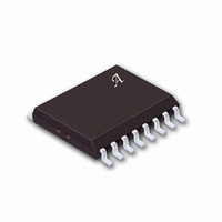
A2557KLB Allegro Microsystems Inc, A2557KLB Datasheet - Page 9

A2557KLB
Manufacturer Part Number
A2557KLB
Description
IC DRIVER QUAD 60V 300MA 16-SOIC
Manufacturer
Allegro Microsystems Inc
Type
Low Sider
Specifications of A2557KLB
Number Of Outputs
4
Input Type
Non-Inverting
Current - Output / Channel
300mA
Current - Peak Output
500mA
Voltage - Supply
4.75 V ~ 5.25 V
Operating Temperature
-40°C ~ 125°C
Mounting Type
Surface Mount
Package / Case
16-SOIC (0.300", 7.5mm Width)
Switch Type
Low Side
Power Switch Family
A2557
Input Voltage
7V
Output Current
300mA
Mounting
Surface Mount
Supply Current
30mA
Package Type
SOIC W
Operating Temperature (min)
-40C
Operating Temperature Classification
Automotive
Pin Count
16
Lead Free Status / RoHS Status
Contains lead / RoHS non-compliant
On-state Resistance
-
Lead Free Status / RoHS Status
Not Compliant, Contains lead / RoHS non-compliant
Available stocks
Company
Part Number
Manufacturer
Quantity
Price
Company:
Part Number:
A2557KLB
Manufacturer:
CMD
Quantity:
5 510
Part Number:
A2557KLB
Manufacturer:
ALLEGRO/雅丽高
Quantity:
20 000
Company:
Part Number:
A2557KLBT
Manufacturer:
ALLEGRO
Quantity:
1 150
Company:
Part Number:
A2557KLBTR-T
Manufacturer:
TE
Quantity:
4 000
Part Number:
A2557KLBTR-T
Manufacturer:
ALLEGRO/雅丽高
Quantity:
20 000
A2557
Inductive load driver
Bifi lar (unipolar) stepper motors (and other inductive loads)
can be driven directly. The internal diodes prevent damage to
the output transistors by suppressing the high-voltage spikes
that occur when turning off an inductive load. For rapid current
decay (fast turn-off speeds), the use of Zener diodes will raise
the fl yback voltage and improve performance. However, the
peak voltage must not exceed the specifi ed minimum sustaining
voltage (V
Over-current conditions
In the event of a shorted load, or stalled motor, the load current
will attempt to increase. As described above, the drive current to
the affected output stage is linearly reduced, causing the output
to go linear (limiting the load current to about 500 mA). As the
junction temperature of the output stage increases, the thermal-
shutdown circuit will shut off the affected output. If the fault
condition is corrected, the output driver will return to its normal
saturated condition.
SUPPLY
0
NORMAL LAMP IN-RUSH CURRENT
+ V
I
TRIP
Z
+ V
THERMAL GRADIENT SENSING
CURRENT LIMIT
F
< V
CIRCUIT DESCRIPTION AND APPLICATION (continued)
TIME
O(SUS)
).
NOT TO SCALE
Dwg. WP-008
with Fault Detection and Sleep Mode
Fault diagnostics
A pull-up resistor or current source is required on the FAULT
output. This can be connected to whatever supply level the fol-
lowing circuitry requires (within the specifi cation constraints).
For a 5 V supply (i.e., Vcc) 150 kΩ or greater should be used.
As the fault diagnostic function is to indicate when the output
state is different from the input state for any channel, the FAULT
output waveform will obviously produce a pulse waveform fol-
lowing the combined duty-cycle of all channels showing a fault
condition. There are therefore two basic approaches to using the
function in an application:
•
has a microcontroller then a FAULT low causes an interrupt,
which then initiates a diagnostic sequence to fi nd the culprit
channel. This sequence usually consists of cycling through each
channel one at a time, while monitoring the FAULT output. It
is then easy to determine which channel has the faulty output
and how it is failing (i.e., short to supply, open-circuit or short to
ground). The system may then take whatever action is required,
but could continue with operation of the remaining ‘good’ chan-
nels while disabling signals to the faulty channel.
•
troller in the system then the FAULT output can be set to give an
indication (via a lamp or LED, etc.) of a fault condition which
might be anywhere on the four channels. Because the FAULT
output is dependent on the states of the input and output (four
possibilities) but will only indicate on two of them, the duty
cycle at the FAULT output will refl ect the duty cycle at the faulty
channel’s input (or its inverse, depending upon fault type).
In typical applications (50% duty cycles) a simple solution is to
make the pull-up current on the FAULT output much less than
the pull-down current (60 μA), and add a capacitor to give a
time constant longer than the period of operation. For typical
values, the device will produce a continuous dc output level.
Component values will need to be adjusted to cope with different
conditions.
As an interrupt in a controller-based system. If the system
As a simple ‘common’ fault indication. If there is no con-
Protected Quad Driver
115 Northeast Cutoff
1.508.853.5000; www.allegromicro.com
Allegro MicroSystems, Inc.
Worcester, Massachusetts 01615-0036 U.S.A.
8


