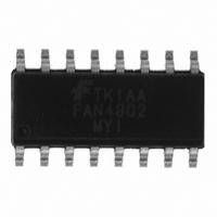
FAN4802MY Fairchild Semiconductor, FAN4802MY Datasheet - Page 21

FAN4802MY
Manufacturer Part Number
FAN4802MY
Description
IC PFC CTRLR AVERAGE CURR 16SOP
Manufacturer
Fairchild Semiconductor
Datasheet
1.FAN4800ANY.pdf
(24 pages)
Specifications of FAN4802MY
Mode
Average Current
Frequency - Switching
64kHz
Current - Startup
30µA
Voltage - Supply
11 V ~ 22 V
Operating Temperature
-40°C ~ 105°C
Mounting Type
Surface Mount
Package / Case
16-SOP
Lead Free Status / RoHS Status
Lead free / RoHS Compliant
Other names
FAN4802MYTR
Available stocks
Company
Part Number
Manufacturer
Quantity
Price
Part Number:
FAN4802MY
Manufacturer:
F
Quantity:
20 000
Part Number:
FAN4802MYI
Manufacturer:
FAIRCHILD/ن»™ç«¥
Quantity:
20 000
© 2008 Fairchild Semiconductor Corporation
FAN4800A/C, FAN4801/02/02L • Rev. 1.0.3
PWM Control (RAMP)
When the PWM section is used in current mode, RAMP
is generally used as the sampling point for a voltage,
representing the current in the primary of the PWM’s
output transformer. The voltage is derived either from a
current sensing resistor or a current transformer. In
voltage mode, RAMP is the input for a ramp voltage
generated by a second set of timing components (R
C
value of approximately 6V. In voltage mode, feed
forward from the PFC output bus is an excellent way to
derive the timing ramp for the PWM stage.
Generating V
After turning on the FAN4800A/C, FAN4801/02/02L at
11V, the operating voltage can vary from 9.3V to 28V.
The threshold voltage of the V
28V and its hysteresis is 1V. When V
OPFC is LOW, and the PWM section is not disturbed.
There are two ways to generate V
power supply around 15V or use bootstrap winding to
self-bias the FAN4800A/C, FAN4801/02/02L system.
The bootstrap winding can be taped from the PFC boost
choke or the transformer of the DC-to-DC stage.
RAMP
) that have a minimum value of 0V and a peak
DD
DD
OVP comparator is
DD
DD
: use auxiliary
reaches 28V,
RAMP
,
21
Leading/Trailing Modulation
Conventional PWM techniques employ trailing-edge
modulation, in which the switch turns on right after the
trailing edge of the system clock. The error amplifier
output is then compared with the modulating ramp up.
The effective duty cycle of the trailing edge modulation
is determined during the on-time of the switch.
In the case of leading-edge modulation, the switch is
turned off exactly at the leading edge of the system
clock. When the modulating ramp reaches the level of
the error amplifier output voltage, the switch is turned
on. The effective duty-cycle of the leading-edge
modulation is determined during off-time of the switch.
www.fairchildsemi.com


