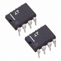
LT1249CN8 Linear Technology, LT1249CN8 Datasheet - Page 3

LT1249CN8
Manufacturer Part Number
LT1249CN8
Description
IC PFC CTRLR AVERAGE CURR 8DIP
Manufacturer
Linear Technology
Datasheet
1.LT1249CN8PBF.pdf
(12 pages)
Specifications of LT1249CN8
Mode
Average Current
Frequency - Switching
100kHz
Current - Startup
250µA
Voltage - Supply
15.5 V ~ 27 V
Operating Temperature
0°C ~ 100°C
Mounting Type
Through Hole
Package / Case
8-DIP (0.300", 7.62mm)
Lead Free Status / RoHS Status
Contains lead / RoHS non-compliant
Available stocks
Company
Part Number
Manufacturer
Quantity
Price
Company:
Part Number:
LT1249CN8
Manufacturer:
LT
Quantity:
5 510
Part Number:
LT1249CN8
Manufacturer:
LT/凌特
Quantity:
20 000
Part Number:
LT1249CN8#PBF
Manufacturer:
LINEAR/凌特
Quantity:
20 000
ELECTRICAL CHARACTERISTICS
Note 1: Absolute Maximum Ratings are those values beyond which the life
of a device may be impaired.
Note 2: Current amplifier is in linear mode with 0V input common mode.
TYPICAL PERFORMANCE CHARACTERISTICS
range, otherwise specifications are at T
VA
PARAMETER
Reference
Reference Output Voltage
Reference Output Voltage Worst Case
Reference Output Voltage Line Regulation
Multiplier
Multiplier Output Current
Multiplier Output Current Offset
Multiplier Max Output Current (I
Multiplier Max Output Voltage (I
Multiplier Gain Constant (Note 3)
I
Oscillator
Oscillator Frequency
Control Pin (CA
Synchronization Frequency Range
Gate Driver
Max GTDR Output Voltage
GTDR Output High
GTDR Output Low (Device Unpowered)
GTDR Output Low (Device Active)
Peak GTDR Current
GTDR Rise and Fall Time
GTDR Max Duty Cycle
AC
OUT
Input Resistance
= 5V, no load on any outputs, unless otherwise noted.
OUT
100
–20
80
60
40
20
0
) Threshold
10
Voltage Amplifier Open-Loop
Gain and Phase
100
M(MAX)
M(MAX)
1k
FREQUENCY (Hz)
PHASE
W
GAIN
)
10k
• R
MOUT
U
100k
A
= 25 C. Maximum operating voltage (V
)
CONDITIONS
T
All Line, Temperature
V
I
R
I
I
I
Duty Cycle = 0
Synchronizing Pulse Low 0.35V on CA
0mA Load, 18V < V
– 200mA Load, 11.5V V
V
200mA Load (Sinking)
10nF from GTDR to GND
1nF from GTDR to GND
1M
AC
AC
AC
AC
A
LOCKOUT
CC
AC
1249 G01
= 25 C, Measured at V
= 100 A, VA
= 450 A, VA
= 450 A, VA
from 50 A to 1mA
= 0V, 50mA Load (Sinking)
= 1M from I
10M
0
–20
–40
–60
–80
–100
–120
< V
CC
The
OUT
OUT
OUT
< V
AC
to GND
CC
MAX
= 5V
= 7V (Note 2)
= 7V (Note 2)
< V
denotes specifications which apply over the operating temperature
SENSE
MAX
CC
Note 3: Multiplier Gain Constant: K =
Note 4: Maximum GTDR output voltage is internally clamped for higher
V
CC
(Note 4)
15V
voltages.
Pin
400
350
300
250
200
150
100
50
MAX
0
OUT
1k
Transconductance of
Current Amplifier
) = 25V, V
g
m
10k
FREQUENCY (Hz)
CC
= 18V, I
100k
V
CC
– 1.25
– 375
7.39
7.32
MIN
– 20
127
1.3
15
75
12
90
– 3.0
I
AC
AC
(VA
1M
= 100 A, CA
– 0.05
OUT
0.035
– 250
– 1.1
I
TYP
100
M
7.5
7.5
1.8
0.9
0.5
1.5
35
32
15
25
96
5
– 1.5)
1249 G02
10M
20
0
–20
–40
–60
–80
–100
–120
–140
2
– 0.96
– 150
MAX
– 0.5
7.68
17.5
125
160
OUT
7.6
2.3
1.5
20
50
1
LT1249
= 3.5V,
UNITS
3
V
kHz
kHz
mV
k
ns
%
–2
V
V
A
A
A
V
V
V
V
V
V
A


