NCP1653PG ON Semiconductor, NCP1653PG Datasheet - Page 17
NCP1653PG
Manufacturer Part Number
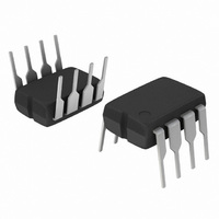
NCP1653PG
Description
IC PFC CONTROLLER CCM 8DIP
Manufacturer
ON Semiconductor
Datasheet
1.NCP1653PG.pdf
(19 pages)
Specifications of NCP1653PG
Mode
Continuous Conduction (CCM)
Frequency - Switching
102kHz
Voltage - Supply
8.75 V ~ 18 V
Operating Temperature
-40°C ~ 125°C
Mounting Type
Through Hole
Package / Case
8-DIP (0.300", 7.62mm)
Switching Frequency
102 KHz (Typ)
Maximum Operating Temperature
+ 125 C
Mounting Style
Through Hole
Minimum Operating Temperature
- 40 C
Lead Free Status / RoHS Status
Lead free / RoHS Compliant
Current - Startup
-
Lead Free Status / Rohs Status
Lead free / RoHS Compliant
Other names
NCP1653PGOS
Available stocks
Company
Part Number
Manufacturer
Quantity
Price

Part Number:
NCP1653PG
Manufacturer:
ON/安森美
Quantity:
20 000


APPENDIX I – SUMMARY OF EQUATIONS IN NCP1653 BOOST PFC
Boost Converter
Input Current Averaged by
Filter Capacitor
Nominal Output Voltage (I
= 200 mA)
Feedback Pin Voltage V
Output Voltage
Inductor Current
Peak−Peak Ripple
Control Current
Switching Frequency
Minimum Inductor for CCM
Input Impedance
Input Power
Output Power
Maximum Input Power when
I
Current Limit
Power Limit
Output Overvoltage
Output Undervoltage
Input Voltage Sense Pin
Resistor R
PWM Comparator
Reference Voltage
control
= 100 mA
Description
vac
FB1
FB
³
Please refer to Figure 11.
V out
V in t V out t 192 mA @ R FB
DI L(pk * pk) t 2 @ I L * 50
P in +
I in + I L * 50
V in
V out(nom) + I FB R FB ) V FB1
I control + I control(max) +
f + 67 or 100 kHz
L u L (CRM) +
Z in +
P out + hP in +
P in(max) + P in +
I L(OCP) +
I L @ V AC t
V out(OVP) + 107% @ V out(nom)
V out(UVP * on) + 8% @ V out(nom)
V out(UVP * off) + 12% @ V out(nom)
R vac u 938 kW and R vac +
V ref + 2.62 V
V out * V in
+
R S R vac I ref V ref
R M R CS V ac V out
R S R vac I ref V ref
t 1 ) t 2
V out
t 2
R M R CS
[ I FB R FB + 200 mA @ R FB
R CS
[ 214 mA @ R FB
R CS
Follower Boost Mode
R S
R S
+
+
V out * V in
hR S R vac I ref V ref
@ 200 mA
[ 16 mA @ R FB
[ 24 mA @ R FB
R vac ) 12 kW
T * t 1
t 1 ) t 2
R S R vac I ref V ref
V out
T
t 1
R M R CS
http://onsemi.com
R M R CS
V out
2
V ac
+
I ref
DI L(pk * pk)
2
t 1
T
R vac ) 12 kW
+ 100 mA
17
@ 3 nA 2
V in
V out
V ac
V out
2
V ac
1
f
192 mA @ R FB t V out t 200 mA @ R FB
Same as Follower Boost Mode
Same as Follower Boost Mode
Same as Follower Boost Mode
Same as Follower Boost Mode
Same as Follower Boost Mode
Same as Follower Boost Mode
Same as Follower Boost Mode
Circuit will enter follower boost region when
maximum power is reached.
Same as Follower Boost Mode
Same as Follower Boost Mode
Same as Follower Boost Mode
Same as Follower Boost Mode
Same as Follower Boost Mode
Same as Follower Boost Mode
I control +
and I control t I control(max) + 100 mA
Z in +
P in +
P out +
2R S R vac I control V ref
2R S R vac V ref
Constant Output Voltage Mode
h2 R S R vac V ref
R M R CS V ac V out
R M R CS
I control(max)
R M R CS
0.04
I control V ac
1 *
V out
I control V ac
V out
R FB I ref
V out
Related parts for NCP1653PG
Image
Part Number
Description
Manufacturer
Datasheet
Request
R

Part Number:
Description:
ON Semiconductor [VOLTAGE REGULATOR]
Manufacturer:
ON Semiconductor
Datasheet:
Part Number:
Description:
357-036-542-201 CARDEDGE 36POS DL .156 BLK LOPRO
Manufacturer:
ON Semiconductor
Datasheet:
Part Number:
Description:
357-036-542-201 CARDEDGE 36POS DL .156 BLK LOPRO
Manufacturer:
ON Semiconductor
Datasheet:
Part Number:
Description:
357-036-542-201 CARDEDGE 36POS DL .156 BLK LOPRO
Manufacturer:
ON Semiconductor
Datasheet:
Part Number:
Description:
357-036-542-201 CARDEDGE 36POS DL .156 BLK LOPRO
Manufacturer:
ON Semiconductor
Datasheet:
Part Number:
Description:
357-036-542-201 CARDEDGE 36POS DL .156 BLK LOPRO
Manufacturer:
ON Semiconductor
Datasheet:
Part Number:
Description:
357-036-542-201 CARDEDGE 36POS DL .156 BLK LOPRO
Manufacturer:
ON Semiconductor
Datasheet:
Part Number:
Description:
357-036-542-201 CARDEDGE 36POS DL .156 BLK LOPRO
Manufacturer:
ON Semiconductor
Datasheet:
Part Number:
Description:
357-036-542-201 CARDEDGE 36POS DL .156 BLK LOPRO
Manufacturer:
ON Semiconductor
Datasheet:
Part Number:
Description:
357-036-542-201 CARDEDGE 36POS DL .156 BLK LOPRO
Manufacturer:
ON Semiconductor
Datasheet:
Part Number:
Description:
357-036-542-201 CARDEDGE 36POS DL .156 BLK LOPRO
Manufacturer:
ON Semiconductor
Datasheet:
Part Number:
Description:
Manufacturer:
ON Semiconductor
Datasheet:
Part Number:
Description:
Manufacturer:
ON Semiconductor
Datasheet:
Part Number:
Description:
Manufacturer:
ON Semiconductor
Datasheet: