DS18B20+PAR Maxim Integrated Products, DS18B20+PAR Datasheet - Page 10
DS18B20+PAR
Manufacturer Part Number
DS18B20+PAR
Description
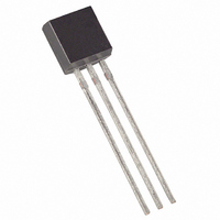
IC THERM MICROLAN PROG-RES TO-92
Manufacturer
Maxim Integrated Products
Specifications of DS18B20+PAR
Function
Thermometer, Thermostat
Topology
Register Bank, Scratchpad
Sensor Type
Internal
Sensing Temperature
-55°C ~ 100°C
Output Type
1-Wire®
Output Alarm
Yes
Output Fan
No
Voltage - Supply
3 V ~ 5.5 V
Operating Temperature
-55°C ~ 100°C
Mounting Type
Through Hole
Package / Case
TO-92-3 (Standard Body), TO-226
Temperature Threshold
Programmable
Full Temp Accuracy
+/- 0.5 C
Digital Output - Bus Interface
1-Wire
Digital Output - Number Of Bits
12 bit
Supply Voltage (max)
5.5 V
Supply Voltage (min)
3 V
Maximum Operating Temperature
+ 125 C
Minimum Operating Temperature
- 55 C
Supply Current
1.5 mA
Lead Free Status / RoHS Status
Lead free / RoHS Compliant


transmitted least significant bit first. All three bytes MUST be written before the master issues a reset, or
the data may be corrupted.
READ SCRATCHPAD [BEh]
This command allows the master to read the contents of the scratchpad. The data transfer starts with the
least significant bit of byte 0 and continues through the scratchpad until the 9
read. If only part of the scratchpad contents is required, the master may issue a reset to terminate reading
at any time.
COPY SCRATCHPAD [48h]
This command copies the contents of the scratchpad T
to EEPROM. Within 10 μs (max) after this command is issued the master must enable a strong pullup on
the 1-Wire bus for at least 10 ms as described in the PARASITE POWER section.
RECALL E
This command recalls the alarm trigger values (T
places the data in bytes 2, 3, and 4, respectively, in the scratchpad memory. The master device can issue
“read time slots” (see the 1-WIRE BUS SYSTEM section) following the Recall E
DS18B20-PAR will indicate the status of the recall by transmitting 0 while the recall is in progress and
1 when the recall is done. The recall operation happens automatically at power-up, so valid data is
available in the scratchpad as soon as power is applied to the device.
DS18B20-PAR Function Command Set Table 4
NOTES:
1. The master must enable a strong pullup on the 1-Wire bus during temperature conversions and copies
2. The master can interrupt the transmission of data at any time by issuing a reset.
3. All three bytes must be written before a reset is issued.
Convert T
Read Scratchpad
Write Scratchpad
Copy Scratchpad
Recall E
from the scratchpad to EEPROM. No other bus activity may take place during this time.
Command
2
2
[B8h]
Initiates temperature
conversion.
Reads the entire scratchpad
including the CRC byte.
Writes data into scratchpad
bytes 2, 3, and 4 (T
configuration registers).
Copies T
configuration register data from
the scratchpad to EEPROM.
Recalls T
configuration register data from
EEPROM to the scratchpad.
TEMPERATURE CONVERSION COMMANDS
H
H
Description
, T
, T
L
L
, and
, and
MEMORY COMMANDS
H
, T
L
, and
10 of 19
H
and T
H
, T
Protocol
L
L
BEh
B8h
4Eh
44h
48h
) and configuration data from EEPROM and
and configuration registers (bytes 2, 3 and 4)
DS18B20-PAR transmits up
After Command is Issued
DS18B20-PAR transmits
to 9 data bytes to master.
bytes to DS18B20-PAR.
Master transmits 3 data
recall status to master.
1-Wire Bus Activity
th
None
None
byte (byte 8 – CRC) is
2
command and the
DS18B20-PAR
Notes
1
2
3
1
Related parts for DS18B20+PAR
Image
Part Number
Description
Manufacturer
Datasheet
Request
R

Part Number:
Description:
IC THERM MICROLAN PROG-RES TO-92
Manufacturer:
Maxim Integrated Products
Datasheet:

Part Number:
Description:
IC THERM MICROLAN PROG-RES TO-92
Manufacturer:
Maxim Integrated Products
Datasheet:
Part Number:
Description:
IC THERM MICROLAN PROG-RES TO-92
Manufacturer:
Maxim Integrated Products
Datasheet:
Part Number:
Description:
IC THERM MICROLAN PROG-RES TO-92
Manufacturer:
Maxim Integrated Products
Datasheet:
Part Number:
Description:
IC THERM MICROLAN PROG-RES TO-92
Manufacturer:
Maxim Integrated Products
Datasheet:
Part Number:
Description:
IC THERM MICROLAN PROG-RES TO-92
Manufacturer:
Maxim Integrated Products
Datasheet:

Part Number:
Description:
1-Wire Parasite-Power Digital Thermometer
Manufacturer:
MAXIM [Maxim Integrated Products]
Datasheet:
Part Number:
Description:
Board Mount Temperature Sensors
Manufacturer:
Maxim Integrated Products
Datasheet:
Part Number:
Description:
Board Mount Temperature Sensors
Manufacturer:
Maxim Integrated Products
Datasheet:
Part Number:
Description:
MAX7528KCWPMaxim Integrated Products [CMOS Dual 8-Bit Buffered Multiplying DACs]
Manufacturer:
Maxim Integrated Products
Datasheet:
Part Number:
Description:
Single +5V, fully integrated, 1.25Gbps laser diode driver.
Manufacturer:
Maxim Integrated Products
Datasheet:
Part Number:
Description:
Single +5V, fully integrated, 155Mbps laser diode driver.
Manufacturer:
Maxim Integrated Products
Datasheet:
Part Number:
Description:
VRD11/VRD10, K8 Rev F 2/3/4-Phase PWM Controllers with Integrated Dual MOSFET Drivers
Manufacturer:
Maxim Integrated Products
Datasheet:
Part Number:
Description:
Highly Integrated Level 2 SMBus Battery Chargers
Manufacturer:
Maxim Integrated Products
Datasheet:
Part Number:
Description:
Current Monitor and Accumulator with Integrated Sense Resistor; ; Temperature Range: -40°C to +85°C
Manufacturer:
Maxim Integrated Products