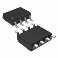
DS1624S+T&R Maxim Integrated Products, DS1624S+T&R Datasheet

DS1624S+T&R
Specifications of DS1624S+T&R
Related parts for DS1624S+T&R
DS1624S+T&R Summary of contents
Page 1
FEATURES Temperature measurements require no external components Measures temperatures from -55°C to +125°C in 0.03125°C increments. Fahrenheit equivalent is -67°F to +257°F in 0.05625°F increments Temperature is read as a 13-bit value (two byte transfer) Converts temperature to digital ...
Page 2
ORDERING INFORMATION ORDERING PACKAGE INFORMATIO MARKING N DS1624 DS1624 DS1624+ DS1624 (See Note) DS1624S DS1624S DS1624S+ DS1624S (See Note) DS1624 in Lead-Free 208 mil 8-pin SO DS1624S/T&R DS1624S DS1624S+T&R DS1624S (See Note) DS1624 in Lead-Free 208 mil 8-pin SO, 2000 ...
Page 3
DS1624 FUNCTIONAL BLOCK DIAGRAM Figure SCL ADDRESS AND I/O CONTROL SDA GND 2-WIRE SERIAL DATA BUS The DS1624 supports a bi–directional two–wire bus and data transmission protocol. A device that sends data onto the ...
Page 4
Data valid: The state of the data line represents valid data when, after a START condition, the data line is stable for the duration of the HIGH period of the clock signal. The data on the line must be changed ...
Page 5
The master device generates all of the serial clock pulses and the START and STOP conditions. A transfer is ended with a STOP condition or with a repeated START condition. Since a repeated START condition is also the beginning of ...
Page 6
OPERATION-MEASURING TEMPERATURE A block diagram of the DS1624 is shown in Figure 1. The DS1624 measures temperatures through the use of an on–board proprietary temperature measurement technique. A block diagram of the temperature measurement circuitry is shown in Figure 4. ...
Page 7
TEMPERATURE MEASURING CIRCUITRY Figure 4 PRESET LOW TEMPERATURE COEFFICIENT OSCILLATOR HIGH TEMPERATURE COEFFICIENT OSCILLATOR Internally, this calculation is performed by the DS1624 to provide 0.03125°C resolution. The temperature reading is provided in a 13–bit, two’s complement reading by issuing READ ...
Page 8
Temperature is represented in the DS1624 in terms of a 0.03125°C LSB, yielding the following 13–bit format: MSB OPERATION AND CONTROL A configuration/status register is used to determine the method of operation of the DS1624 ...
Page 9
PAGE PROGRAM MODE To program the DS1624 the master sends addresses and data to the DS1624 which is the slave. This is done by supplying a START condition followed by the 4–bit device code, the 3–bit slave address, and the ...
Page 10
Access Memory [17h] This command instructs the DS1624 to access its E byte is the value of the word address to be accessed. See OPERATION–MEMORY section for detailed explanations of the use of this protocol and data format following it. ...
Page 11
During the programming cycle the DS1624 will not acknowledge any further accesses to the device until the programming cycle is complete (approximately 10 ms). MEMORY FUNCTION EXAMPLE BUS MASTER DS1624 MODE MODE {Command protocol for configuration register} {Start here} TX ...
Page 12
BUS MASTER DS1624 MODE MODE {Command protocol for writing to EEPROM} {Start here ...
Page 13
BUS MASTER DS1624 MODE MODE NOTES this protocol follows a write and the DS1624 does not acknowledge here, restart the ...
Page 14
ABSOLUTE MAXIMUM RATINGS* Voltage on Any Pin Relative to Ground Operating Temperature Storage Temperature Soldering Temperature * This is a stress rating only and functional operation of the device at these or any other conditions above those indicated in the ...
Page 15
AC ELECTRICAL CHARACTERISTICS PARAMETERS SYMBOL Temperature T TC Conversion Time NV Write Cycle t WR Time EEPROM Writes N EEWR EEPROM Data t EEDR Retention SLK Clock f SCL Frequency Bus Free Time t BUF Between a STOP and START ...
Page 16
AC ELECTRICAL CHARACTERISTICS PARAMETER Input Capacitance NOTES: 1. All voltages are referenced to ground. 2. I/O pins of fast mode devices must not obstruct the SDA and SCL lines specified with SDA pin open ...
Page 17
TIMING DIAGRAM Note: The DS1624 does not delay the SDA line internally with respect to SCL for any length of time TYPICAL PERFORMANCE CURVE DS1624 DIGITAL THERMOMETER AND THERMOSTAT TEMPERATURE READING ERROR TEMPERATURE (deg DS1624 t ...


