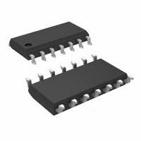
LM2907MX/NOPB National Semiconductor, LM2907MX/NOPB Datasheet - Page 3

LM2907MX/NOPB
Manufacturer Part Number
LM2907MX/NOPB
Description
IC CONVERTER FREQ-VOLTAGE 14SOIC
Manufacturer
National Semiconductor
Type
Frequency to Voltager
Datasheet
1.LM2907M-8NOPB.pdf
(22 pages)
Specifications of LM2907MX/NOPB
Frequency - Max
10kHz
Linearity
±0.3%
Mounting Type
Surface Mount
Package / Case
14-SOIC (0.154", 3.90mm Width)
Converter Function
FVC
Power Supply Requirement
Single
Single Supply Voltage (typ)
12V
Single Supply Voltage (max)
28V
Dual Supply Voltage (typ)
Not RequiredV
Dual Supply Voltage (min)
Not RequiredV
Dual Supply Voltage (max)
Not RequiredV
Operating Temperature (min)
-40C
Operating Temperature (max)
85C
Operating Temperature Classification
Industrial
Package Type
SOIC N
Lead Free Status / RoHS Status
Lead free / RoHS Compliant
Other names
LM2907MX
Available stocks
Company
Part Number
Manufacturer
Quantity
Price
Company:
Part Number:
LM2907MX/NOPB
Manufacturer:
EXAR
Quantity:
6 222
TACHOMETER
V
V
I
I
K
OP/AMP COMPARATOR
V
I
ZENER REGULATOR
2
3
BIAS
Symbol
OH
OL
, I
OS
Absolute Maximum Ratings
If Military/Aerospace specified devices are required,
please contact the National Semiconductor Sales Office/
Distributors for availability and specifications.
Electrical Characteristics
V
Note 1: For operation in ambient temperatures above 25°C, the device must be derated based on a 150°C maximum junction temperature and a thermal resistance
of 101°C/W junction to ambient for LM2907-8 and LM2917-8, and 79°C/W junction to ambient for LM2907-14 and LM2917-14.
Note 2: Hysteresis is the sum +V
Note 3: V
the two factors that cause the tachometer gain constant to vary from 1.0.
Note 4: Be sure when choosing the time constant R1 × C1 that R1 is such that the maximum anticipated output voltage at pin 3 can be reached with I
maximum value for R1 is limited by the output resistance of pin 3 which is greater than 10 MΩ typically.
Supply Voltage
Supply Current (Zener Options)
Collector Voltage
Differential Input Voltage
Input Voltage Range
3
CC
Tachometer
Op Amp/Comparator
Tachometer
= 12 V
LM2907-8, LM2917-8
LM2907, LM2917
OH
Input Thresholds
Hysteresis
Offset Voltage
Input Bias Current
Pin 2
Pin 2
Output Current
Leakage Current
Gain Constant
Linearity
Input Common-Mode Voltage
Voltage Gain
Output Sink Current
Output Source Current
Saturation Voltage
Regulator Voltage
Series Resistance
Temperature Stability
Total Supply Current
is equal to ¾ × V
DC
LM2907/LM2917
LM2907-8/LM2917-8
, T
A
= 25°C, see test circuit
Parameter
CC
− 1 V
TH
− (−V
BE
, V
TH
OL
), offset voltage is their difference. See test circuit.
is equal to ¼ × V
V
V
V
V
V
V
V2 = V3 = 6.0V (Note 4)
I2 = 0, V3 = 0
(Note 3)
f
V
V
V
V
I
I
I
R
IN
SINK
SINK
SINK
IN
IN
IN
IN
IN
IN
IN
IN
C
E
DROP
0.0V to +28V
= 1 kHz, 5 kHz, 10 kHz (Note 5)
= 1.0
= V
= 250 mVp-p @ 1 kHz (Note 2)
= 250 mVp-p @ 1 kHz (Note 2)
= 250 mVp-p @ 1 kHz (Note 2)
= ±50 mV
= +125 mV
= −125 mV
= 6.0V
= 6.0V
(Note 1)
= 5 mA
= 20 mA
= 50 mA
CC
CC
= 470Ω
25 mA
− 1 V
−2.0
±28V
28V
28V
28V
28V
DC
BE
DC
DC
therefore V
Conditions
(Note 3)
(Note 3)
3
OH
Power Dissipation
Operating Temperature Range
Storage Temperature Range
Soldering Information
− V
Op Amp/Comparator
LM2907-8, LM2917-8
LM2907-14, LM2917-14
See (Note 1)
Dual-In-Line Package
Small Outline Package
Soldering (10 seconds)
Vapor Phase (60 seconds)
Infrared (15 seconds)
OL
= V
CC
/2. The difference, V
−1.0
Min
±10
140
0.9
40
0
OH
− V
7.56
10.5
Typ
±25
180
200
3.5
0.1
8.3
2.3
1.0
0.3
0.1
1.0
3.8
30
50
50
10
+1
5
3
OL
, and the mirror gain, I
V
−65°C to +150°C
CC
−40°C to +85°C
Max
+1.0
±40
240
500
0.1
1.1
0.5
1.0
1.5
10
15
10
15
−1.5V
1
6
0.0V to +28V
www.national.com
1200 mW
1580 mW
3
× R1. The
260°C
215°C
220°C
2
mV/°C
/I
Units
V/mV
3
mV
mV
mV
mV
mV
mA
mA
mA
μA
μA
μA
nA
, are
%
Ω
V
V
V
V
V
V
V


