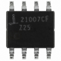
ISL21007CFB825Z-TK Intersil, ISL21007CFB825Z-TK Datasheet - Page 16

ISL21007CFB825Z-TK
Manufacturer Part Number
ISL21007CFB825Z-TK
Description
IC VOLT REF FGA LV 2.5V 8-SOIC
Manufacturer
Intersil
Series
FGA™r
Datasheet
1.ISL21007DFB812Z-TK.pdf
(18 pages)
Specifications of ISL21007CFB825Z-TK
Reference Type
Series
Voltage - Output
2.5V
Tolerance
±1mV
Temperature Coefficient
5ppm/°C
Voltage - Input
2.7 ~ 5.5 V
Number Of Channels
1
Current - Quiescent
150µA
Operating Temperature
-40°C ~ 125°C
Mounting Type
Surface Mount
Package / Case
8-SOIC (3.9mm Width)
Rohs Compliant
YES
Lead Free Status / RoHS Status
Lead free / RoHS Compliant
Current - Output
-
Current - Cathode
-
Other names
ISL21007CFB825Z-TKTR
Available stocks
Company
Part Number
Manufacturer
Quantity
Price
Company:
Part Number:
ISL21007CFB825Z-TK
Manufacturer:
Intersil
Quantity:
1 000
Turn-On Time
The ISL21007 devices have low supply current and thus the
time to bias up internal circuitry to final values will be longer
than with higher power references. Normal turn-on time is
typically 120µs. This is shown in Figure 10. Circuit design
must take this into account when looking at power-up delays
or sequencing.
Temperature Coefficient
The limits stated for temperature coefficient (tempco) are
governed by the method of measurement. The overwhelming
standard for specifying the temperature drift of a reference is to
measure the reference voltage at two temperatures, take the
total variation, (V
extremes of measurement (T
divided by the nominal reference voltage (at T = +25°C) and
multiplied by 10
specifying temperature coefficient.
Typical Application Circuits
6
HIGH
to yield ppm/°C. This is the “Box” method for
– V
LOW
HIGH
), and divide by the temperature
16
– T
LOW
V
). The result is
FIGURE 56. PRECISION 2.500V 50mA REFERENCE
IN
= +5.0V
ISL21007
V
OUT
= 2.500V
GND
V
IN
R = 200Ω
V
ISL21007
OUT
Output Voltage Adjustment
The output voltage can be adjusted up or down by 2.5% by
placing a potentiometer from V
the wiper to the TRIM pin. The TRIM input is high impedance,
so no series resistance is needed. The resistor in the
potentiometer should be a low tempco (<50ppm/°C) and the
resulting voltage divider should have very low tempco
<5ppm/°C. A digital potentiometer such as the ISL95810
provides a low tempco resistance and excellent resistor and
tempco matching for trim applications. See Figure 58 and
TB473 for further information.
V
2N2905
IN
= 5.0V
0.001µF
FIGURE 55. HANDLING HIGH LOAD CAPACITANCE
0.1µF
2.5V/50mA
10µF
ISL21007
GND
V
OUT
IN
to ground, and connecting
V
O
0.01µF
December 13, 2007
FN6326.7
2kΩ
10µF


