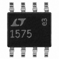
LT1575CS8#PBF Linear Technology, LT1575CS8#PBF Datasheet - Page 7

LT1575CS8#PBF
Manufacturer Part Number
LT1575CS8#PBF
Description
IC LDO REG ADJ SINGLE 8-SOIC
Manufacturer
Linear Technology
Type
Positive Adjustabler
Datasheet
1.LT1575CN8-2.8.pdf
(20 pages)
Specifications of LT1575CS8#PBF
Number Of Outputs
1
Voltage - Output
Adjustable
Current - Supply
12mA
Voltage - Input
10 ~ 20 V
Operating Temperature
0°C ~ 70°C
Package / Case
8-SOIC (3.9mm Width)
Primary Input Voltage
12V
No. Of Pins
8
Output Current
1.5mA
Voltage Regulator Case Style
SOIC
Operating Temperature Range
0°C To +70°C
Svhc
No SVHC (15-Dec-2010)
Rohs Compliant
Yes
Lead Free Status / RoHS Status
Lead free / RoHS Compliant
Available stocks
Company
Part Number
Manufacturer
Quantity
Price
PIN
SHDN (Pin 1): This is a multifunction shutdown pin that
provides GATE drive latchoff capability. A 15 A current
source, that turns on when current limit is activated,
charges a capacitor placed in series with SHDN to GND
and performs a current limit time-out function. The pin is
also the input to a comparator referenced to V
When the pin pulls above V
gate drive to the external MOSFET off. The comparator
typically has 100mV of hysteresis and the Shutdown pin
can be pulled low to reset the latchoff function. This pin
provides overvoltage protection or thermal shutdown
protection when driven from various resistor divider
schemes.
V
the majority of internal circuitry and provides sufficient
gate drive compliance for the external N-channel MOSFET.
The typical supply voltage is 12V with 12.5mA of quiescent
current. The maximum operating V
minimum operating V
MOSFET at max. I
output swing).
GND (Pin 3): Analog Ground. This pin is also the negative
sense terminal for the internal 1.21V reference. Connect
external feedback divider networks that terminate to GND
and frequency compensation components that terminate
to GND directly to this pin for best regulation and perfor-
mance.
FB (Pin 4): This is the inverting input of the error amplifier
for the adjustable voltage LT1575. The noninverting input
is tied to the internal 1.21V reference. Input bias current
for this pin is typically 0.6 A flowing out of the pin. This pin
is normally tied to a resistor divider network to set output
voltage. Tie the top of the external resistor divider directly
to the output voltage for best regulation performance.
OUT (Pin 4): This is the inverting input of the error
amplifier for the fixed voltage LT1575. The fixed voltage
parts contain a precision resistor divider network to set
output voltage. The typical resistor divider current is 1mA
into the pin. Tie this pin directly to the output voltage for
best regulation performance.
COMP (Pin 5): This is the high impedance gain node of the
error amplifier and is used for external frequency compen-
IN
U
(Pin 2): This is the input supply for the IC that powers
FUNCTIONS
U
OUT
U
IN
+ 1.6V (worst-case V
is set by V
REF
, the comparator latches the
IN
OUT
is 20V and the
+ V
REF
IN
GS
to GATE
(1.21V).
of the
sation. The transconductance of the error amplifier is 15
millimhos and open-loop voltage gain is typically 84dB.
Frequency compensation is generally performed with a
series RC network to ground.
GATE (Pin 6): This is the output of the error amplifier that
drives N-channel MOSFETs with up to 5000pF of “effec-
tive” gate capacitance. The typical open-loop output
impedance is 2 . When using low input capacitance
MOSFETs (< 1500pF), a small gate resistor of 2 to 10
dampens high frequency ringing created by an LC reso-
nance that is created by the MOSFET gate’s lead induc-
tance and input capacitance. The GATE pin delivers up to
50mA for a few hundred nanoseconds when slewing the
gate of the N-channel MOSFET in response to output load
current transients.
INEG (Pin 7): This is the negative sense terminal of the
current limit amplifier. A small sense resistor is connected
in series with the drain of the external MOSFET and is
connected between the IPOS and INEG pins. A 50mV
threshold voltage in conjunction with the sense resistor
value sets the current limit level. The current sense resis-
tor can be a low value shunt or can be made from a piece
of PC board trace. If the current limit amplifier is not used,
tie the INEG pin to IPOS to defeat current limit. An
alternative is to ground the INEG pin. This action disables
the current limit amplifier and additional internal circuitry
activates the timer circuit on the SHDN pin if the GATE pin
swings to the V
a “sense-less” current limit function.
IPOS (Pin 8): This is the positive sense terminal of the
current limit amplifier. Tie this pin directly to the main
input voltage from which the output voltage is regulated.
The typical input voltage is a 5V logic supply. This pin is
also the input to a comparator on the fixed voltage ver-
sions that monitors the input/output differential voltage of
the external MOSFET. If this differential voltage is less than
0.5V, then the SHDN timer is not allowed to start even if the
GATE is at the V
normally as the input voltage is ramping up, even with very
slow ramp rates.
IN
IN
rail. This allows the regulator to start up
rail. This option provides the user with
LT1575/LT1577
7


