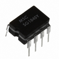
SG1845Y Microsemi Analog Mixed Signal Group, SG1845Y Datasheet - Page 2

SG1845Y
Manufacturer Part Number
SG1845Y
Description
IC PWM CURRENT MODE 8-DIP
Manufacturer
Microsemi Analog Mixed Signal Group
Datasheet
1.SG3845M.pdf
(12 pages)
Specifications of SG1845Y
Pwm Type
Current Mode
Number Of Outputs
1
Frequency - Max
500kHz
Duty Cycle
50%
Voltage - Supply
8.3 V ~ 30 V
Buck
Yes
Boost
No
Flyback
No
Inverting
No
Doubler
No
Divider
No
Cuk
No
Isolated
Yes
Operating Temperature
-55°C ~ 125°C
Package / Case
8-DIP
Frequency-max
500kHz
Lead Free Status / RoHS Status
Lead free by exemption / RoHS compliant by exemption
Available stocks
Company
Part Number
Manufacturer
Quantity
Price
Company:
Part Number:
SG1845Y/883B
Manufacturer:
SMD
Quantity:
6 220
Part Number:
SG1845Y/DESC
Manufacturer:
MSC
Quantity:
20 000
2
SG1844/SG1845 Series
Supply Voltage (I
Supply Voltage (Low Impedance Source) ........................................................ 30V
Output Current (Peak) ....................................................................................... ±1A
Output Current (Continuous) ....................................................................... 350mA
Output Energy (Capacitive Load) ....................................................................... 5µJ
Analog Inputs (V
Error Amp Output Sink Current ..................................................................... 10mA
Operating Junction Temperature
Storage Temperature Range .......................................................... -65°C to +150°C
Lead Temperature (Soldering, 10 Seconds) .................................................. 300°C
RoHS / Pb-free Peak Package Solder Reflow Temp. (40 second max. exposure)............................... 260°C (+0, -5)
Note 1. Exceeding these ratings could cause damage to the device.
Note 2. All voltages are with respect to Pin 5. All currents are positive into the specified
M PACKAGE:
N PACKAGE:
DM PACKAGE:
D PACKAGE:
Y PACKAGE:
J PACKAGE:
F PACKAGE:
L PACKAGE:
Junction Temperature Calculation: T
The θ
system. All of the above assume no ambient airflow.
THERMAL RESISTANCE-JUNCTION TO AMBIENT, θ θ θ θ θ
THERMAL RESISTANCE-JUNCTION TO AMBIENT, θ θ θ θ θ
THERMAL RESISTANCE-JUNCTION TO AMBIENT, θ θ θ θ θ
THERMAL RESISTANCE-JUNCTION TO AMBIENT, θ θ θ θ θ
THERMAL RESISTANCE-JUNCTION TO AMBIENT, θ θ θ θ θ
THERMAL RESISTANCE-JUNCTION TO AMBIENT, θ θ θ θ θ
THERMAL RESISTANCE-JUNCTION TO CASE, θ θ θ θ θ
THERMAL RESISTANCE-JUNCTION TO AMBIENT, θ θ θ θ θ
THERMAL RESISTANCE-JUNCTION TO CASE, θ θ θ θ θ
THERMAL RESISTANCE-JUNCTION TO AMBIENT, θ θ θ θ θ
Hermetic (J, Y, F, L Packages) ................................................................... 150°C
Plastic (N, M, D, DM Packages) ................................................................ 150°C
JA
numbers are guidelines for the thermal performance of the device/pc-board
A B S O L U T E M A X I M U M R AT I N G S
terminal.
FB
CC
, I
< 30mA) ............................................................... Self Limiting
SENSE
) ................................................................ -0.3V to +6.3V
T H E R M A L D ATA
P R O D U C T D A T A B O O K 1 9 9 6 / 1 9 9 7
J
= T
C
A
U R R E N T
+ (P
P
R O D U C T I O N
D
JC
JC
x θ
JA
JA
JA
JA
JA
JA
JA
JA
JA
).
- M
O D E
(Notes 1 & 2)
P W M C
D
165°C/W
120°C/W
130°C/W
145°C/W
120°C/W
95°C/W
65°C/W
80°C/W
80°C/W
35°C/W
A T A
O N T R O L L E R
S
H E E T
1. COM
2. V
3. I
4. R
5. OWER GND
4
5
6
7
8
SENSE
M Package: RoHS / Pb-free 100% Matte Tin Lead Finish
FB
T
N Package: RoHS / Pb-free 100% Matte Tin Lead Finish
/C
T
3
9
10
PACKAGE PIN OUTS
2
RoHS / Pb-free 100% Matte Tin Lead Finish
COM
RoHS / Pb-free 100% Matte Tin Lead Finish
COM
11
R
1 20 19
N.C.
N.C.
I
N.C.
R
T
COM
SENSE
COM
I
/C
SENSE
T
V
R
/C
R
V
12 13
I
N.C.
N.C.
I
N.C.
FB
SENSE
T
T
M & Y PACKAGE
SENSE
/C
T
FB
/C
V
V
J & N PACKAGE
T
DM PACKAGE
FB
FB
T
T
D PACKAGE
F PACKAGE
L PACKAGE
(Top View)
(Top View)
(Top View)
(Top View)
(Top View)
(Top View)
1
2
3
4
1
2
3
4
5
6
7
1
2
3
4
5
1
2
3
4
5
6
7
1
2
3
4
18
17
16
15
14
14
13
12
11
10
10
8
7
6
5
14
13
12
11
10
9
8
8
7
6
5
9
8
9
8
7
6
1. N.C.
2. N.C.
3. COM .
4. N.C.
5. V
6. N.C.
7. I
8. R
9. N.C.
10. N.C.
V
V
OUT UT
GND
V
N.C.
V
V
OUT UT
GROUND
REF
CC
V
V
OUT UT
GND
SENSE
OWER GND
REF
CC
C
V
N.C.
V
V
OUT UT
GND
FB
T
REF
CC
/C
WR GND
REF
CC
C
T
Copyright © 2000
Rev. 1.6c
10.V
9. V
8. V
7. OUT UT
6. GND
11. N.C.
12. WR GND
13. GND
14. N.C.
15. OUT UT
16. N.C.
17. V
18. V
19. N.C.
20. V
REF
CC
C
C
CC
REF


