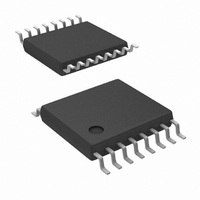
LM5041AMTC/NOPB National Semiconductor, LM5041AMTC/NOPB Datasheet - Page 11

LM5041AMTC/NOPB
Manufacturer Part Number
LM5041AMTC/NOPB
Description
IC CTRLR PWM CASCADED 16TSSOP
Manufacturer
National Semiconductor
Series
PowerWise®r
Datasheet
1.LM5041AMTCNOPB.pdf
(16 pages)
Specifications of LM5041AMTC/NOPB
Pwm Type
Current Mode
Number Of Outputs
1
Frequency - Max
1MHz
Duty Cycle
91%
Voltage - Supply
15 V ~ 90 V
Buck
Yes
Boost
Yes
Flyback
No
Inverting
Yes
Doubler
No
Divider
No
Cuk
No
Isolated
Yes
Operating Temperature
-40°C ~ 125°C
Package / Case
16-TSSOP
Frequency-max
1MHz
For Use With
LM5041EVAL - BOARD EVALUATION LM5041
Lead Free Status / RoHS Status
Lead free / RoHS Compliant
Other names
*LM5041AMTC
*LM5041AMTC/NOPB
LM5041AMTC
*LM5041AMTC/NOPB
LM5041AMTC
Push-Pull Outputs
PWM Comparator
The PWM comparator compares the slope compensated
current ramp signal to the loop error voltage from the internal
error amplifier (COMP pin). This comparator is optimized for
speed in order to achieve minimum controllable duty cycles.
The comparator polarity is such that 0V on the COMP pin will
produce zero duty cycle in the buck stage.
Error Amplifier
An internal high gain wide-bandwidth error amplifier is pro-
vided within the LM5041A. The amplifier’s non-inverting in-
put is tied to a 0.75V reference. The inverting input is con-
nected to the FB pin. In non-isolated applications the power
converter output is connected to the FB pin via the voltage
setting resistors. Loop compensation components are con-
nected between the COMP and FB pins. For most isolated
applications the error amplifier function is implemented on
the secondary side of the converter and the internal error
amp is not used. The internal error amplifier is configured as
an open drain output and can be disabled by connecting the
FB pin to ground. An internal 5kΩ pull-up resistor between
the 5V reference and COMP can be used as the pull-up for
an opto-coupler in isolated applications.
Current Limit/Current Sense
The LM5041A provides cycle-by-cycle over-current protec-
tion. If the voltage at the CS comparator (CS pin voltage plus
slope comp voltage) exceeds 0.5V the present buck stage
duty cycle is terminated (cycle by cycle current limit). A small
RC filter located near the controller is recommended to filter
current sense signals at the CS pin. An internal MOSFET
discharges the external CS pin for an additional 50ns at the
beginning of each cycle to reduce the leading edge spike
that occurs when the buck stage MOSFET is turned on.
The LM5041A current sense and PWM comparators are
very fast, and may respond to short duration noise pulses.
Layout considerations are critical for the current sense filter
and sense resistor. The capacitor associated with the CS
(Continued)
11
filter must be placed close to the device and connected
directly to the pins of the controller (CS and GND). If a
current sense transformer is used, both leads of the trans-
former secondary should be routed to the sense resistor,
which should also be located close to the IC. A resistor may
be used for current sensing instead of a transformer, located
in the push-pull transistor sources, but a low inductance type
of resistor is required. When designing with a sense resistor,
all of the noise sensitive low power grounds should be
connected together around the IC and a single connection
should be made to the high current power ground (sense
resistor ground point).
Oscillator and Sync Capability
The LM5041A oscillator is set by a single external resistor
connected between the RT pin and GND. To set a desired
oscillator frequency (F), the necessary RT resistor can be
calculated from:
The buck stage will switch at the oscillator frequency and
each push-pull output will switch at half the oscillator fre-
quency in a push-pull configuration. The LM5041A can also
be synchronized to an external clock. The external clock
must have a higher frequency than the free running fre-
quency set by the RT resistor. The clock signal should be
capacitively coupled into the RT pin with a 100pF capacitor.
A peak voltage level greater than 3V is required for detection
of the sync pulse. The sync pulse width should be set in the
15 to 150ns range by the external components. The RT
resistor is always required, whether the oscillator is free
running or externally synchronized. The voltage at the RT pin
is internally regulated to 2V. The RT resistor should be
located very close to the device and connected directly to the
pins of the IC (RT and GND).
20137804
www.national.com


