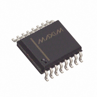
MAX758ACWE+ Maxim Integrated Products, MAX758ACWE+ Datasheet - Page 9

MAX758ACWE+
Manufacturer Part Number
MAX758ACWE+
Description
IC REG PWM ADJ 16-SOIC
Manufacturer
Maxim Integrated Products
Type
Step-Down (Buck), PWM - Current Moder
Datasheet
1.MAX750ACSA.pdf
(16 pages)
Specifications of MAX758ACWE+
Internal Switch(s)
Yes
Synchronous Rectifier
No
Number Of Outputs
1
Voltage - Output
1.25 ~ 16 V
Current - Output
750mA
Frequency - Switching
160kHz
Voltage - Input
4 ~ 16 V
Operating Temperature
0°C ~ 70°C
Mounting Type
*
Package / Case
16-SOIC (0.300", 7.5mm Width)
Voltage - Supply
4 V ~ 16 V
Frequency-max
190kHz
Duty Cycle
87%
Pwm Type
Current Mode
Buck
Yes
Boost
No
Flyback
No
Inverting
No
Doubler
No
Divider
No
Cuk
No
Isolated
No
Lead Free Status / RoHS Status
Lead free / RoHS Compliant
tors’ leakage currents rises sharply. The actual design
limit for standby current is much less than the 100µA
specified in the Electrical Characteristics (see the
Standby Current vs. Temperature graph in the Typical
Operating Characteristics ). However, testing to tighter
limits is prohibitive because the current takes several
seconds to settle to a final value. For normal operation,
connect SHDN to V+. Coming out of shutdown mode
initiates a soft-start cycle.
The input voltage, output voltage, load current, and
inductor value determine whether the IC operates in
continuous or discontinuous mode. As the inductor
value or load current decreases, or the input voltage
increases, the MAX750A/MAX758A tend to operate in
discontinuous-conduction mode (DCM). In DCM, the
inductor-current slope is steep enough so it decays to
zero before the end of the transistor off-time. In contin-
uous-conduction mode (CCM), the inductor current
never decays to zero, which is typically more efficient
than DCM. CCM allows the MAX750A/MAX758A to
deliver maximum load current, and is also slightly less
noisy than DCM because the ripple current in the out-
put capacitor is smaller.
The +1.23V bandgap reference supplies up to 100µA
at REF. Connect a 0.01µF bypass capacitor from REF
to GND.
Figure 2. Block Diagram of Soft-Start Circuitry
510k
FROM SHDN
C1
R1
SS
_______________________________________________________________________________________
Continuous-/Discontinuous-
MAX750A
MAX758A
1M
±35%
1.23V
Internal Reference
SS CLAMP
Conduction Modes
Current-Mode PWM Regulators
Adjustable, Step-Down,
The internal oscillator of the MAX750A typically oper-
ates at 170kHz (160kHz for the MAX758A). The Typical
Operating Characteristics indicate stability of the oscil-
lator frequency over temperature and supply voltage.
Figure 3 shows the MAX750A/MAX758A configured for a
standard 5V step-down application. Table 2 lists the com-
ponents for the desired operating temperature range.
These circuits are useful in systems that require high cur-
rent at high efficiency and are powered by an unregulated
supply, such as a battery or wall-plug AC-DC transformer.
They will operate over the entire line, load, and tempera-
ture ranges using the single set of component values
shown in Figure 3 and listed in Table 2.
The MAX750A/MAX758A require no inductor design
because they are tested in-circuit, and are guaranteed
to deliver the power specified in the Electrical
Characteristics with high efficiency using a single
100µH (MAX75_AC) or 33µH (MAX75_AE/AM) inductor
The inductor’s incremental saturation-current rating
should be greater than 1A, and its DC resistance
should be less than 0.8Ω. Table 2 lists inductor types
and suppliers for various applications. The surface-
mount inductors and the larger-size through-hole
inductors have nearly equivalent efficiencies.
The MAX750A/MAX758A have outputs adjustable from
1.25V to the input voltage. To set the output voltage,
connect a voltage divider to the feedback input pin
(CC) as shown in Figure 3. The output voltage is set by
R2 and R3 as follows:
Let R3 be any resistance in the 10kΩ to 20kΩ range
(typically 10kΩ), then
Output tolerance over temperature is ±4.5% plus exter-
nal resistor tolerances.
The primary criterion for selecting the output filter
capacitor is low equivalent series resistance (ESR).
The product of the inductor-current variation and the
ESR of the output capacitor determines the amplitude
of the sawtooth ripple seen on the output voltage. In
addition, the ESR of the output filter capacitor should
be minimized to maintain AC stability. The ESR of the
capacitor should be less than 0.25Ω to keep the output
ripple less than 50mVp-p over the entire current range
(using a 100µH inductor). Capacitor ESR ususally rises
__________Applications Information
R2 = R3 [((V
Output Filter Capacitor Selection
Adjusting the Output Voltage
OUT
/1.22V) - 1)]
Inductor Selection
Oscillator
9


