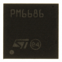
PM6686TR STMicroelectronics, PM6686TR Datasheet - Page 26

PM6686TR
Manufacturer Part Number
PM6686TR
Description
IC CTLR DUAL STEP DOWN VFQFPN32
Manufacturer
STMicroelectronics
Datasheet
1.PM6686TR.pdf
(50 pages)
Specifications of PM6686TR
Applications
Controller, Notebook Computers
Voltage - Input
5.5 ~ 28 V
Number Of Outputs
2
Operating Temperature
-40°C ~ 85°C
Mounting Type
Surface Mount
Package / Case
32-VFQFN, 32-VFQFPN
Output Voltage
5.5 V
Output Current
100 mA
Output Power
4.3 mW
Input Voltage
5.5 V to 28 V
Switching Frequency
33 KHz
Mounting Style
SMD/SMT
Maximum Operating Temperature
+ 85 C
Minimum Operating Temperature
- 40 C
Lead Free Status / RoHS Status
Lead free / RoHS Compliant
Voltage - Output
-
Lead Free Status / Rohs Status
Lead free / RoHS Compliant
Other names
497-8522-2
Available stocks
Company
Part Number
Manufacturer
Quantity
Price
Company:
Part Number:
PM6686TR
Manufacturer:
st
Quantity:
2 069
Part Number:
PM6686TR
Manufacturer:
ST
Quantity:
20 000
Device description
8.1.2
26/50
Constant on time control (COT)
PM6686 implements a pseudo-fixed frequency algorithm using the COT architecture. The
two sections are completely independent with separated switching controllers (SMPS).
The COT architecture bases its algorithm on the output ripple derived across the output
capacitor's ESR. The controller has an internal on time (T
output voltage valley: when VOUT reaches the regulation value a new T
duration is given by the following equation:
Equation 2
Where T
VIN is the input voltage.
The duty cycle in a buck converter is:
Equation 3
The switching frequency in continuous current mode (CCM) is:
Equation 4
The switching frequency is theoretically constant, but in a real application it depends on
parasitic voltage drops that occur during the charging path (high-side switch resistance,
inductor resistance (DCR)) and discharging path (low-side switch resistance, DCR). As a
result the switching frequency increases as a function of the load current. The following
table shows the switching frequencies that can be selected through TON pin:
Table 8.
VREF2 or open
GND
TON
VCC
ON
is the on time duration, K is a constant, V
Frequency configurations
Frequency
200 kHz
400 kHz
400 kHz
Doc ID 15281 Rev 4
f
SMPS 1
SW
=
T
T
T
SW
T
ON
ON
D
ON
=
=
2.5 µs
2.5 µs
=
5 µs
D
K
K
K
⋅
=
V
⋅
V
V
OUT
V
V
V
OUT
IN
V
V
IN
OUT
OUT
IN
IN
OUT
=
K
1
ON
is the sensed output voltage and
Frequency
) generator triggered on the
300 kHz
300 kHz
500 kHz
SMPS 2
ON
starts. The T
3.33 µs
3.33 µs
2 µs
K
PM6686
ON


