LT1580CT Linear Technology, LT1580CT Datasheet - Page 11
LT1580CT
Manufacturer Part Number
LT1580CT
Description
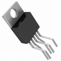
IC LDO REGULATOR 7A ADJ TO220-5
Manufacturer
Linear Technology
Datasheet
1.LT1580CTPBF.pdf
(16 pages)
Specifications of LT1580CT
Applications
Converter, Intel Pentium®
Voltage - Input
1.79 ~ 6 V
Number Of Outputs
1
Voltage - Output
1.25 ~ 4.65 V
Operating Temperature
0°C ~ 125°C
Mounting Type
Through Hole
Package / Case
TO-220-5 (Bent and Staggered Leads)
Lead Free Status / RoHS Status
Contains lead / RoHS non-compliant
Available stocks
Company
Part Number
Manufacturer
Quantity
Price

Company:
Part Number:
LT1580CT
Manufacturer:
LT
Quantity:
5 510
Part Number:
LT1580CT
Manufacturer:
LT/凌特
Quantity:
20 000
Part Number:
LT1580CT#PBF
Manufacturer:
LINEAR/凌特
Quantity:
20 000
Company:
Part Number:
LT1580CT7-2.5
Manufacturer:
LT
Quantity:
5
Company:
Part Number:
LT1580CT7-2.5
Manufacturer:
LT
Quantity:
5 510
Part Number:
LT1580CT7-2.5
Manufacturer:
LINEAR/凌特
Quantity:
20 000


APPLICATIONS
low dropout applications the power dissipation will be less
than 12W.
The power in the device is made up of two main compo-
nents: the power in the output transistor and the power in
the drive circuit. The additional power in the control circuit
is negligible.
The power in the drive circuit will be equal to:
where I
I
I
I
Characteristics curves.
The power in the output transistor is equal to:
The total power is equal to:
Junction-to-case thermal resistance is specified from the
IC junction to the bottom of the case directly below the die.
This is the lowest resistance path for heat flow. Proper
mounting is required to ensure the best possible thermal
flow from this area of the package to the heat sink. Thermal
compound at the case-to-heat sink interface is strongly
recommended. If the case of the device must be electroni-
cally isolated, a thermally conductive spacer can be used
as long as the added contribution to thermal resistance is
considered. Please consult Linear Technology’s “ Mount-
ing Considerations for Power Semiconductors,” 1990
Linear Applications Handbook, Volume 1 , Pages RR3-1 to
RR3-20. Note that the case of the LT1580 is electrically
connected to the output.
OUT
CONTROL
CONTROL
P
P
P
DRIVE
OUTPUT
TOTAL
/58 (max).
CONTROL
vs I
= (V
is a function of output current. A curve of
= P
= (V
OUT
DRIVE
CONTROL
POWER
is equal to between I
can be found in the Typical Performance
U
+ P
OUTPUT
– V
– V
INFORMATION
U
OUT
OUT
)(I
)(I
OUT
CONTROL
W
)
OUT
)
/100 (typ) and
U
The following example illustrates how to calculate
maximum junction temperature. Using an LT1580 and
assuming:
V
V
V
T
Power dissipation under these conditions is equal to:
Junction temperature will be equal to:
For the Control section:
For the Power section:
In both cases the junction temperature is below the
maximum rating for the respective sections, ensuring
reliable operation.
A
CONTROL
POWER
OUT
CASE-HEATSINK
Total Power Dissipation = P
P
I
P
P
Total Power Dissipation = 4.05W
T
T
93 C < 125 C = T
T
101 C < 150 C = T
= 70 C,
CONTROL
J
J
J
DRIVE
DRIVE
OUTPUT
= 70 C + 4.05W (4 C/W + 1 C/W + 2.7 C/W) = 101 C
= 70 C + 4.05W(4 C/W + 1 C/W + 0.65 C/W) = 93 C
= 2.5V, Iout = 4A,
= T
(max continuous) = 3.465V (3.3V + 5%),
A
= (V
= (5.25V – 2.5V)(69mA) = 190mW
(max continuous) = 5.25V (5V + 5%),
+ P
= (V
= ( 3.465V – 2.5V)(4A) = 3.9W
= I
HEATSINK
TOTAL
CONTROL
OUT
= 1 C/W (with thermal compound)
POWER
/58 = 4A/58 = 69mA
(
JMAX
JMAX
= 4 C/W,
HEATSINK
LT1580/LT1580-2.5
– V
– V
for Control Section
OUT
OUT
for Power Section
) (I
)(I
DRIVE
+
OUT
CONTROL
CASE-HEATSINK
)
+ P
OUTPUT
)
+
11
JC
)
Related parts for LT1580CT
Image
Part Number
Description
Manufacturer
Datasheet
Request
R

Part Number:
Description:
7A/ Very Low Dropout Regulator
Manufacturer:
Linear Technology
Datasheet:

Part Number:
Description:
7A, Very Low Dropout Regulator
Manufacturer:
LINER [Linear Technology]
Datasheet:
Part Number:
Description:
CD ROM LINEARVIEW DATASHEETS
Manufacturer:
Linear Technology

Part Number:
Description:
Standalone Linear Li-Ion Battery Charger with Thermal Regulation in ThinSOT
Manufacturer:
Linear Technology Corporation
Datasheet:
Part Number:
Description:
Low noise, high frequency, 8th order linear phase lowpass filter
Manufacturer:
Linear Technology Corporation
Datasheet:
Part Number:
Description:
Manufacturer:
Linear Technology Corporation
Datasheet:
Part Number:
Description:
Manufacturer:
Linear Technology Corporation
Datasheet:
Part Number:
Description:
Manufacturer:
Linear Technology Corporation
Datasheet:
Part Number:
Description:
Manufacturer:
Linear Technology Corporation
Datasheet:
Part Number:
Description:
Manufacturer:
Linear Technology Corporation
Datasheet:
Part Number:
Description:
Manufacturer:
Linear Technology Corporation
Datasheet:
Part Number:
Description:
Manufacturer:
Linear Technology Corporation
Datasheet:
Part Number:
Description:
Dual and Quad, JFET Input Precision High Speed Op Amps
Manufacturer:
Linear Technology Corporation
Datasheet:
Part Number:
Description:
Manufacturer:
Linear Technology Corporation
Datasheet:
Part Number:
Description:
1, 2, 6 and 8 Channel, 10-Bit Serial I/O Data Acquisition Systems
Manufacturer:
Linear Technology Corporation
Datasheet: