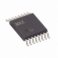
MAX3353EEUE+T Maxim Integrated Products, MAX3353EEUE+T Datasheet - Page 9

MAX3353EEUE+T
Manufacturer Part Number
MAX3353EEUE+T
Description
IC CHARGE PUMP USB OTG 16TSSOP
Manufacturer
Maxim Integrated Products
Datasheet
1.MAX3353EEUET.pdf
(21 pages)
Specifications of MAX3353EEUE+T
Applications
Charge Pump, USB
Voltage - Input
2.6 ~ 5.5 V
Number Of Outputs
2
Operating Temperature
-40°C ~ 85°C
Mounting Type
Surface Mount
Package / Case
16-TSSOP
Maximum Operating Temperature
+ 85 C
Mounting Style
SMD/SMT
Minimum Operating Temperature
- 40 C
Lead Free Status / RoHS Status
Lead free / RoHS Compliant
Voltage - Output
-
Lead Free Status / Rohs Status
Lead free / RoHS Compliant
charge pump on and off to power V
register 2 (V
through a 5kΩ resistor. Figure 2 and Table 2 show
power control.
USB OTG defines the HNP, where the default host (A
Device) can pass the host responsibilities off to the
default peripheral (B Device). This protocol can be han-
dled entirely by the firmware and controlling logic that dri-
ves the OTG transceiver. The MAX3353E has the option
to automatically perform some of the required signaling
for some of the timing-critical events in the HNP process.
The automatic signaling used by the A Device, when it
transfers host control to the B Device, is defined by the
OTG transceiver supplement and is known as autocon-
nect. Autoconnect allows the transceiver to automatically
connect the A Device’s D+ pullup resistor during HNP.
Autoconnect is enabled when the MAX3353E is config-
ured as an A Device (ID_IN = 0) and the BDISC_ACONN
control bit is set.
The MAX3353E also has the capability to automate the
signaling used by the B Device when it assumes host
control from the A Device. This autoresponse is not speci-
fied by the OTG-transceiver supplement. Autoresponse
causes the B Device to automatically assert a bus reset
by driving a single-ended zero (SE0: both D+ and D- dri-
ven low) onto USB in response to the A Device connect-
ing its D+ pullup resistor. Autoresponse is enabled when
the MAX3353E is configured as a B Device and the
BDISC_ACONN control bit is set.
Note: In a system, D+ and D- are also driven by a trans-
ceiver in an ASIC or other device. The autoresponse
mode should not be used unless the system designer
can ensure that there is no bus conflict between the
transceiver and the MAX3353E driving USB to SE0.
When the MAX3353E is configured as an A Device
(ID_IN = GND), it can enable autodetect by setting
BDISC_ACONN to one. This should be done after the
USB is in the suspend state (>3ms with no traffic). The
MAX3353E monitors D+/D- for an SE0. The presence of
the SE0 indicates that the B Device has disconnected
its pullup resistor, the first step in HNP. When SE0 is
detected, the MAX3353E automatically turns on its
internal pullup resistor to the D+ line within 3ms. There
are two ways for firmware to ascertain that the
MAX3353E has automatically turned on its D+ pullup
during HNP:
1) The A_HNP status bit goes high when the D+ pullup
is automatically connected during HNP
USB On-the-Go Charge Pump with Switchable
BUS_DISCHG
Autoconnect and Autoresponse
_______________________________________________________________________________________
) is used to discharge V
Autoconnect Details
BUS
. Bit 4 in control
BUS
Pullup/Pulldown Resistors
2) The A_HNP_EN control bit is set, and an interrupt is
By clearing BDISC_ACONN bit, the D+ pullup is discon-
nected. After a successful autoconnect operation, the
firmware should set the DP_PULLUP control bit before
clearing the BDISC_ACONN bit; this ensures that the
D+ pullup remains connected.
Note: The autoconnect works only if MAX3353E is not
in shutdown.
When the MAX3353E is configured as a B Device
(ID_IN = open), setting the BDISC_ACONN control bit
enables the autoresponse feature. Using this feature,
the MAX3353E automatically issues a USB bus reset
when the A Device becomes a peripheral. Firmware
can take advantage of the autoresponse feature of the
MAX3353E by doing the following:
• Ensure that the system transceiver is in USB-sus-
• Wait for B_HNP to go high; output SE0 from the
Note: The autoresponse works only if the MAX3353E is
not in shutdown.
Session request protocol (SRP) is designed to allow
the A Device (default host) to conserve power by turn-
ing off V
(default peripheral) can request the A Device to turn
V
The B Device must initiate SRP in two ways: data-line
and V
on and off the pullup resistor on D+ to implement
data-line pulsing. Firmware can also be used to turn on
and off a current source to implement V
BUS
issued as the D+ pullup is connected (see also the
Interrupt Logic section).
pend mode. Wait until the USB-suspend conditions
are met (no USB activity for >3ms). Enable auto-
response. Set the BDISC_ACONN control bit. Signal
a USB disconnect. Firmware clears the DP_PULLUP
control bit, which disconnects the D+ pullup resis-
tor. At this point, the MAX3353E waits at least 25µs
before enabling its internal USB line monitor to
detect if the A Device has attached its D+ pullup;
this ensures that the D+ line is not high due to the
residual effect of the B Device pullup. When the A
Device has connected its D+ pullup, the MAX3353E
issues a bus reset (SE0) and the B_HNP status bit
goes high.
ASIC or other device on D+/D-. Disable autore-
sponse. By clearing BDISC_ACONN bit, the SE0
generator is turned off. The SE0 is maintained by the
system USB transceiver.
on and initiate a new session through SRP.
BUS
BUS
pulsing. Firmware is responsible for turning
when there is no USB traffic. The B Device
Autoresponse Details
SRP V
BUS
BUS
Pulsing
pulsing.
9


