EL5825IL Intersil, EL5825IL Datasheet - Page 6
EL5825IL
Manufacturer Part Number
EL5825IL
Description
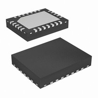
IC VREF GEN 8CH TFT-LCD 24-QFN
Manufacturer
Intersil
Datasheet
1.EL5825IR.pdf
(12 pages)
Specifications of EL5825IL
Applications
Converter, TFT, LCD
Voltage - Input
4.5 ~ 16.5 V
Number Of Outputs
8
Voltage - Output
0.5 ~ 14.95 V
Operating Temperature
-40°C ~ 85°C
Mounting Type
Surface Mount
Package / Case
24-VQFN Exposed Pad, 24-HVQFN, 24-SQFN, 24-DHVQFN
Lead Free Status / RoHS Status
Contains lead / RoHS non-compliant
Available stocks
Company
Part Number
Manufacturer
Quantity
Price

Part Number:
EL5825ILZ
Manufacturer:
INTERSIL
Quantity:
20 000
Company:
Part Number:
EL5825ILZ-T13
Manufacturer:
INTERSIL
Quantity:
2 944
Company:
Part Number:
EL5825ILZ-T7
Manufacturer:
ROHM
Quantity:
84 000


Product Description
The EL5825 provides a versatile method of providing the
reference voltages that are used in setting the transfer
characteristics of LCD display panels.
The V/T (Voltage/Transmission) curve of the LCD panel
requires that a correction is applied to make it linear;
however, if the panel is to be used in more than one
application, the final curve may differ for different
applications.
By using the EL5825, this curve can be changed to optimize
its characteristics according to the required application of the
display product.
Each of the reference voltage outputs can be set with a
10-bit resolution. These outputs are available to within
100mV of the power rails of the EL5825.
As all of the output buffers are identical, it is also possible to
use the EL5825 for applications other than LCDs where 8
voltage references are required that can be set to a 10-bit
accuracy.
Serial Interface
The EL5825 is programmed through a three-wire serial
interface. The start and stop conditions are defined by the
ENA signal. While the ENA is low, the data on the SDI (serial
data input) pin is shifted into the 16-bit shift register on the
positive edge of the SCLK (serial clock) signal. The MSB (bit
15) is loaded first and the LSB (bit 0) is loaded last (see
Table 1). After the full 16-bit data has been loaded, the ENA
is pulled high and the addressed output channel is updated.
The SCLK is disabled internally when the ENA is high. The
SCLK must be low before the ENA is pulled low.
To facilitate the system designs that use multiple EL5825
chips, a buffered serial output of the shift register (SDO pin)
is available. Data appears on the SDO pin at the 16th falling
SCLK edge after being applied to the SDI pin.
To control the multiple EL5825 chips from a single three-wire
serial port, just connect the ENA pins and the SCLK pins
together, connect the SDO pin to the SDI pin on the next
chip. While the ENA is held low, the 16m-bit data is loaded to
the SDI input of the first chip. The first 16-bit data will go to
the last chip and the last 16-bit data will go to the first chip.
While the ENA is held high, all addressed outputs will be
updated simultaneously.
The Serial Timing Diagram and parameters table show the
timing requirements for three-wire signals.
The serial data has a minimum length of 16 bits, the MSB
(most significant bit) is the first bit in the signal. The bits are
6
EL5825
allocated to the following functions (also refer to the Control
Bits Logic Table)
• Bit 15 is always set to a zero
• Bit 14 controls the source of the clock, see the next
• Bits 13 through 10 select the channel to be written to,
• The 10-bit data is on bits 9 through 0. Some examples of
section for details
these are binary coded with channel A = 0, and channel
H = 7
data words are shown in the table of Serial Programming
Examples
B15
B14
B13
B12
B11
B10
BIT
B9
B8
B7
B6
B5
B4
B3
B2
B1
B0
TABLE 1. CONTROL BITS LOGIC TABLE
Oscillator
NAME
Test
A3
A2
A1
A0
D9
D8
D7
D6
D5
D4
D3
D2
D1
D0
Always 0
0 = Internal, 1 = External
Channel Address (don’t care)
Channel Address
Channel Address
Channel Address
Data
Data
Data
Data
Data
Data
Data
Data
Data
Data
DESCRIPTION
June 24, 2005
FN7005.4
Related parts for EL5825IL
Image
Part Number
Description
Manufacturer
Datasheet
Request
R

Part Number:
Description:
Reference Voltage Generator, 8-Channel, TFT/LCD, VS = 4.5/18V, 8mA, Rail to Rail, 10 Bit Resolution
Manufacturer:
Intersil Corporation
Datasheet:
Part Number:
Description:
Intersil Corporation [CMOS Serial Controller Interface]
Manufacturer:
Intersil Corporation
Datasheet:
Part Number:
Description:
Manufacturer:
Intersil Corporation
Datasheet:
Part Number:
Description:
357-036-542-201 CARDEDGE 36POS DL .156 BLK LOPRO
Manufacturer:
Intersil Corporation
Datasheet:
Part Number:
Description:
1024-Word x 4-Bit LSI Static RAM
Manufacturer:
Intersil Corporation
Datasheet:
Part Number:
Description:
General Purpose NPN Transistor Arrays FN341.4
Manufacturer:
Intersil Corporation
Datasheet:
Part Number:
Description:
CMOS 16-Bit Microprocessor
Manufacturer:
Intersil Corporation
Datasheet:
Part Number:
Description:
Manufacturer:
Intersil Corporation
Datasheet:
Part Number:
Description:
Manufacturer:
Intersil Corporation
Datasheet:
Part Number:
Description:
Manufacturer:
Intersil Corporation
Datasheet:
Part Number:
Description:
Manufacturer:
Intersil Corporation
Datasheet:
Part Number:
Description:
CMOS 6-Bit Latch and Decoder Memory Interfaces
Manufacturer:
Intersil Corporation
Datasheet:
Part Number:
Description:
CA3046General Purpose NPN Transistor Arrays
Manufacturer:
Intersil Corporation
Datasheet:
Part Number:
Description:
Manufacturer:
Intersil Corporation
Datasheet:
Part Number:
Description:
TR909 DLC/FLC SLIC with Low Power Standby
Manufacturer:
Intersil Corporation
Datasheet: