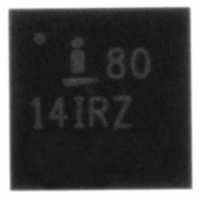
ISL8014IRZ-T Intersil, ISL8014IRZ-T Datasheet - Page 13

ISL8014IRZ-T
Manufacturer Part Number
ISL8014IRZ-T
Description
IC REG SYNC BUCK 4A 1.0MHZ 16QFN
Manufacturer
Intersil
Type
Step-Down (Buck)r
Datasheet
1.ISL8014IRZ-T.pdf
(16 pages)
Specifications of ISL8014IRZ-T
Internal Switch(s)
Yes
Synchronous Rectifier
Yes
Number Of Outputs
1
Voltage - Output
0.8 ~ 5.5 V
Current - Output
4A
Frequency - Switching
1MHz
Voltage - Input
2.7 ~ 5.5 V
Operating Temperature
-40°C ~ 85°C
Mounting Type
Surface Mount
Package / Case
16-VQFN Exposed Pad, 16-HVQFN, 16-SQFN, 16-DHVQFN
Rohs Compliant
YES
Lead Free Status / RoHS Status
Lead free / RoHS Compliant
Power - Output
-
Other names
ISL8014IRZ-TTR
Available stocks
Company
Part Number
Manufacturer
Quantity
Price
Short-Circuit Protection
The short-circuit protection SCP comparator monitors the
VFB pin voltage for output short-circuit protection. When
the VFB is lower than 0.2V, the SCP comparator forces
the PWM oscillator frequency to drop to 1/3 of the normal
operation value. This comparator is effective during
start-up or an output short-circuit event.
PG
During power-up, the open-drain power good output
holds low for about 1ms after V
regulation voltage. The PG output also serves as a 1ms
delayed the Power Good signal when the pull-up resistor
R
Soft Start-Up
The soft-start-up reduces the inrush current during the
start-up. The soft-start block outputs a ramp reference to
the input of the error amplifier. This voltage ramp limits
the inductor current as well as the output voltage speed
so that the output voltage rises in a controlled fashion.
When VFB is less than 0.2V at the beginning of the
soft-start, the switching frequency is reduced to 1/3 of
the nominal value so that the output can start up
smoothly at light load condition. During soft-start, the IC
operates in the SKIP mode to support pre-biased output
condition.
UVLO
When the input voltage is below the undervoltage lock-
out (UVLO) threshold, the regulator is disabled. To adjust
the voltage level of power on and UVLO, use a resistive
divider across EN. The input voltage programming
resistor R
referred to in Figure 38. The value of R
between 10kΩ and 100kΩ.
Enable
The enable (EN) input allows the user to control the
turning on or off the regulator for purposes such as
power-up sequencing. When the regulator is enabled,
there is typically a 600µs delay for waking up the
bandgap reference and then the soft-start-up begins. It
is recommended that the EN voltage should be kept logic
low (less than 400mV), until V
Figures 38 and 39 for suggested circuit implementation
with V
1
is installed.
IN
FIGURE 38. EXTERNAL RESISTOR DIVIDER
slew rate.
4
will depend on on the bottom resistor R
+
-
EN
1V
13
IN
OUT
reaches 2.5V. Refer to
V
IN
reaches the
R5
R4
5
is typically
C
5
, as
ISL8014
Let T equal the rise time of V
R
high threshold) when V
2.5V. Set R
to determine R
Where V
Then select C such that the equivalent time constant is at
least 2x the rise time, T. This will delay the EN voltage
enough so that the overall EN voltage is less than 400mV
by the time V
Where T is the rise time of V
As an example, let V
Then R
used to insure that V
was <400mV.
Discharge Mode (Soft-Stop)
When a transition to shutdown mode occurs or the VIN
UVLO is set, the outputs discharge to GND through an
internal 100Ω switch.
Power MOSFETs
The power MOSFETs are optimized for best efficiency.
The ON-resistance for the P-MOSFET is typically 50mΩ
and the ON-resistance for the N-MOSFET is typically
50mΩ.
100% Duty Cycle
The ISL8014 features 100% duty cycle operation to
maximize the battery life. When the battery voltage
drops to a level that the ISL8014 can no longer maintain
the regulation at the output, the regulator completely
turns on the P-MOSFET. The maximum dropout voltage
under the 100% duty-cycle operation is the product of
the load current and the ON-resistance of the P-MOSFET.
R
C
FIGURE 39. CIRCUIT IMPLEMENTATION WITH V
4
4
≥
such that the voltage is 1.4V (minimum enable logic
=
------------------- -
R
2 T
R
-------------------------------------------- -
4
•
5
||
4
R
⋅
IN
= 56.2kΩ, R
(
5
V
1.4V
5
IN
is greater than or equal to 2.5V.
between 10kΩ to 100kΩ, and use Equation 1
SLEW RATE
–
IN
1.4V
4
2.5V
:
reaches 2.5V. Use Equation 2 to get C:
)
IN
5
IN
= 71.5kΩ, and C = 0.68µF are
IN
= 5V with rise time, T = 10ms.
T
was >2.5V and the EN voltage
is equal to or greater than
VIN
EN
<400mV
IN
IN
. Select the ratio of R
t (TIME)
November 23, 2009
(EQ. 2)
(EQ. 1)
FN6576.4
IN
5
and


