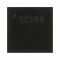
SC198MLTRT Semtech, SC198MLTRT Datasheet - Page 9

SC198MLTRT
Manufacturer Part Number
SC198MLTRT
Description
IC DUAL DC-DC BUCK CONV 20-MLPQ
Manufacturer
Semtech
Type
Step-Down (Buck)r
Datasheet
1.SC198MLTRT.pdf
(16 pages)
Specifications of SC198MLTRT
Internal Switch(s)
Yes
Synchronous Rectifier
Yes
Number Of Outputs
2
Voltage - Output
Programmable
Current - Output
600mA
Frequency - Switching
1MHz
Voltage - Input
2.7 ~ 5.5 V
Operating Temperature
-40°C ~ 85°C
Mounting Type
Surface Mount
Package / Case
20-MLPQ
Lead Free Status / RoHS Status
Lead free / RoHS Compliant
Power - Output
-
Other names
SC198MLTR
Available stocks
Company
Part Number
Manufacturer
Quantity
Price
Part Number:
SC198MLTRT
Manufacturer:
SEMTECH/美国升特
Quantity:
20 000
Inductor Selection
The SC198 was designed for optimum performance when
using a 4.7μH inductor. The magnitude of the inductor
current ripple is dependent on the inductor value and can
be determined by the following equation:
This equation demonstrates the relationship between in-
put voltage, output voltage, and inductor ripple current.
The inductor should also have a low DCR to minimize the
conduction losses and maximize effi ciency. The minimum
DC current rating of the inductor should be equal to the
maximum load current plus half of the inductor current
ripple as shown by the following equation:
Final inductor selection will depend on various design con-
siderations such as effi ciency, EMI, size and cost. Table B
lists some manufacturers of practical inductor options.
Capacitor Selection
Input Capacitor
The source input current to a buck converter is non-con-
tinuous. To prevent large input voltage ripple a low ESR
ceramic capacitor is required. A minimum value of 4.7μF
should be used for suffi cient input voltage fi ltering and a
22μF MLCC may be used for optimum input voltage fi lter-
ing.
Output Capacitor
A 4.7μF ceramic capacitor is the minimum recommended
for the output fi lter capacitor. A capacitor value of at least
10μF is recommended if the part will be used in power-
save mode. Output voltage ripple is dominated by the fi l-
ter capacitance ESR as shown in the following equation:
POWER MANAGEMENT
Applications Information (Cont.)
© 2007 Semtech Corp.
ΔI
I
V
L(PK)
OUT(P-P)
L
= ———
= I
L × f
V
OUT(MAX)
= ΔI
OUT
OSC
L
(
× ESR
+ ——
1 + ———
ΔI
2
V
L
COUT
OUT
V
IN
NOT RECOMMENDED FOR NEW DESIGN
)
9
Capacitors with X7R or X5R ceramic dielectric are strongly
recommended for their low ESR and superior temperature
and voltage characteristics. Y5V capacitors should not be
used as their temperature coeffi cients make them unsuit-
able for this application. Table C lists some manufactur-
ers of recommended capacitor options.
www.semtech.com
SC198


