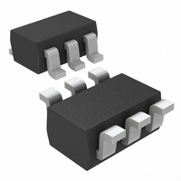
MAX4840EXT+T Maxim Integrated Products, MAX4840EXT+T Datasheet - Page 3

MAX4840EXT+T
Manufacturer Part Number
MAX4840EXT+T
Description
IC CTLR OVP 5.8V SC70-6
Manufacturer
Maxim Integrated Products
Type
Overvoltage Protection Controllerr
Datasheet
1.MAX4840EXTT.pdf
(11 pages)
Specifications of MAX4840EXT+T
Applications
Cell Phones, Digital Cameras, Media Players
Mounting Type
Surface Mount
Package / Case
SC-70-6, SC-88, SOT-363
Lead Free Status / RoHS Status
Lead free / RoHS Compliant
Other names
MAX4840EXT+T
MAX4840EXT+TTR
MAX4840EXT+TTR
ELECTRICAL CHARACTERISTICS (continued)
(V
= +25°C.) (Note 1)
Note 1: All parts are 100% tested at +25°C. Electrical limits across the full temperature range are guaranteed by design and
(V
unless otherwise noted.)
TIMING
Startup Delay
FLAG Blanking Time
GATE Turn-On Time
GATE Turn-Off Time
FLAG Assertion Delay
Initial Overvoltage Fault Delay
Disable Time
IN
IN
600
500
400
300
200
100
0
= +5V (MAX4838A/MAX4840A), V
= +5V (MAX4838A/MAX4840A), V
0
SUPPLY CURRENT vs. INPUT VOLTAGE
correlation.
PARAMETER
5
INPUT VOLTAGE (V)
10
_______________________________________________________________________________________
Overvoltage-Protection Controllers with
15
20
25
SYMBOL
IN
IN
30
t
t
BLANK
t
t
START
t
GOFF
FLAG
t
GON
t
OVP
DIS
= +4V (MAX4842A), T
= +4V (MAX4842A); Si9936DY external MOSFET in back-to-back configuration; T
1000
100
0.1
10
V
V
V
V
C
V
(MAX4838A/MAX4840A), V
from 4V to 6V at 3V/µs (MAX4842A),
V
V
(MAX4838A/MAX4840A), V
from 4V to 6V at 3V/µs (MAX4842A),
V
V
(MAX4838A/MAX4840A), V
from 0V to 6V (MAX4842A), I
I
V
PD
1
IN
GATE
GA TE
GA TE
IN
GATE
IN
FLAG
IN
EN
GA TE
3.5
, Figure 3
> V
increasing from 5V to 8V at 3V/µs
increasing from 5V to 8V at 3V/µs
increasing from 0 to 8V
= 2.4V , V
= 0.3V to 8V ( M AX 4838A/M AX 4840A) ,
= 0.3V to 6V ( M AX 4842A) ,
= 1500p F, Fi g ur e 1
= 0.4V, Figure 2
> 0.3V, V
= 0.3V, C
UVLO
vs. OUTPUT VOLTAGE
4.0
BACK-TO-BACK MOSFETS
REVERSE CURRENT
OUTPUT VOLTAGE (V)
, V
GA TE
A
CONDITIONS
GATE
SINGLE MOSFET
= -40°C to +85°C, unless otherwise noted. Typical values are at T
FLAG
GATE
= 0.3V , Fi g ur e 4
4.5
> 0.3V, Figure 1
> 2.4V, Figure 1
Typical Operating Characteristics
= 1500pF, Figure 2
5.0
IN
IN
IN
GATE
increasing
increasing
increasing
= 80% of
5.5
12
9
6
3
0
MIN
Status FLAG
20
20
3
GATE VOLTAGE vs. INPUT VOLTAGE
4
MAX4838A/MAX4840A
TYP
5.8
1.5
50
50
10
MAX4840A
6
2
INPUT VOLTAGE (V)
5
MAX
80
80
20
6
MAX4838A
A
= +25°C,
7
UNITS
ms
ms
ms
µs
µs
µs
µs
8
3
A


