PKD01BY Analog Devices Inc, PKD01BY Datasheet - Page 5
PKD01BY
Manufacturer Part Number
PKD01BY
Description
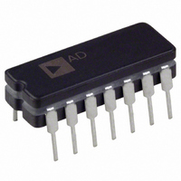
IC MONO PEAK DETECTOR R&H 14CDIP
Manufacturer
Analog Devices Inc
Datasheet
1.PKD01FP.pdf
(18 pages)
Specifications of PKD01BY
Rohs Status
RoHS non-compliant
Applications
*
Mounting Type
Through Hole
Package / Case
14-CDIP (0.300", 7.62mm)
Power Supply Requirement
Dual
Single Supply Voltage (typ)
Not RequiredV
Single Supply Voltage (min)
Not RequiredV
Single Supply Voltage (max)
Not RequiredV
Mounting
Through Hole
Pin Count
14
Lead Free Status / RoHS Status
Not Compliant


WAFER TEST LIMITS
Parameter
“g
COMPARATOR
DIGITAL INPUTS–RST, DET
MISCELLANEOUS
g
COMPARATOR
MISCELLANEOUS
NOTES
1
2
3
Guaranteed by design.
DET = 1, RST = 0.
Due to limited production test times, the droop current corresponds to junction temperature (T
point. Since most devices (in use) are on for more than 1 second, ADI specifies droop rate for ambient temperature (T
specification is correlated to the junction temperature (T
Ambient (T
m
m
Zero-Scale Error
Input Offset Voltage
Input Bias Current
Input Offset Current
Voltage Gain
Common-Mode Rejection Ratio
Power Supply Rejection Ratio
Input Voltage Range
Feedthrough Error
Input Offset Voltage
Input Bias Current
Input Offset Current
Voltage Gain
Common-Mode Rejection Ratio
Power Supply Rejection Ratio
Input Voltage Range
Low Output Voltage
“OFF” Output Leakage Current
Output Short-Circuit Current
Logic “1” Input Voltage
Logic “0” Input Voltage
Logic “1” Input Current
Logic “0” Input Current
Droop Rate
Output Voltage Swing Amplifier C
Short-Circuit Current Amplifier C
Power Supply Current
Slew Rate
Acquisition Time
Response Time
Switch Aperture Time
Switching Time
Buffer Slew Rate
AMPLIFIERS A, B
” AMPLIFIERS A, B
A
) temperature specifications are not subject to production testing.
3
1
1
1
1
(@ V
2
S
=
15 V, C
Symbol
V
V
I
I
A
V
V
I
I
A
V
V
I
I
V
V
I
I
V
V
I
I
t
t
t
t
SR
CMRR
PSRR
CMRR
PSRR
SR
A
A
AP
S
B
OS
B
OS
L
SC
INH
INL
SC
SY
ZS
OS
V
CM
OS
V
CM
OL
H
L
DR
OP
J
) value. ADI has a droop current cancellation circuit that minimizes droop current at high temperature.
H
= 1000 pF, T
Conditions
R
–10 V ≤ V
± 9 V ≤ V
∆V
2 kΩ Pull-Up Resistor to 5 V
–10 V ≤ V
± 9 V ≤ V
I
V
V
V
V
T
T
R
No Load
0.1% Accuracy, 20 V Step, A
0.01% Accuracy, 20 V Step, A
5 mV Overdrive, 2 kΩ Pull-Up Resistor to 5 V
R
SINK
L
OUT
OUT
H
L
L
L
J
A
IN
= 25°C,
= 10 kΩ, V
= 0.4 V
= 2.5 kΩ
= 2.5 kΩ
= 25°C
= 3.5 V
= 20 V, DET = 1, RST = 0
≤ 5 mA, Logic GND = 5 V
A
= 5 V
= 5 V
= 25 C, unless otherwise noted.)
S
S
CM
CM
≤ ± 18 V
≤ ± 18 V
≤ +10 V
≤ +10 V
O
= ± 10 V
J
). The droop current vs. time (after power-on) curve clarifies this
VCL
VCL
= 1
= 1
A
) also. The warmed-up (T
PKD01N
Limit
7
6
250
75
10
74
76
± 11.5
66
3
1000
300
3.5
82
76
± 11.5
0.4
–0.2
80
45
7
2
0.8
1
10
0.1
0.20
± 11
40
7
9
0.5
41
45
150
75
50
2.5
A
) droop current
PKD01
Unit
mV max
mV max
nA max
nA max
V/mV min
dB min
dB min
V min
dB min
mV max
nA max
nA max
V/mV min
dB min
dB min
V min
V max
V min
µA max
mA min
mA min
V min
V max
µA max
µA max
mV/ms max
mV/ms max
V min
mA max
mA min
mA max
V/µs
µs
µs
ns
ns
ns
V/µs
Related parts for PKD01BY
Image
Part Number
Description
Manufacturer
Datasheet
Request
R

Part Number:
Description:
±1.7g Dual-Axis IMEMS Accelerometer Evaluation Board
Manufacturer:
Analog Devices Inc
Datasheet:

Part Number:
Description:
Inertial Sensor Evaluation System
Manufacturer:
Analog Devices Inc
Datasheet:
Part Number:
Description:
Manufacturer:
Analog Devices Inc
Datasheet:
Part Number:
Description:
Manufacturer:
Analog Devices Inc
Datasheet:
Part Number:
Description:
Manufacturer:
Analog Devices Inc
Datasheet:
Part Number:
Description:
Manufacturer:
Analog Devices Inc
Datasheet:
Part Number:
Description:
Manufacturer:
Analog Devices Inc
Datasheet:
Part Number:
Description:
Manufacturer:
Analog Devices Inc
Datasheet:
Part Number:
Description:
Manufacturer:
Analog Devices Inc
Datasheet:
Part Number:
Description:
Manufacturer:
Analog Devices Inc
Datasheet:
Part Number:
Description:
Manufacturer:
Analog Devices Inc
Datasheet:
Part Number:
Description:
Manufacturer:
Analog Devices Inc
Datasheet:
Part Number:
Description:
Manufacturer:
Analog Devices Inc
Datasheet: