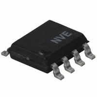
IL612-3E NVE, IL612-3E Datasheet - Page 7

IL612-3E
Manufacturer Part Number
IL612-3E
Description
ISOLATOR TX/RX CMOS 8SOIC
Manufacturer
NVE
Series
IsoLoop®r
Datasheet
1.IL610-1E.pdf
(21 pages)
Specifications of IL612-3E
Inputs - Side 1/side 2
1/1
Number Of Channels
2
Isolation Rating
2500Vrms
Voltage - Supply
3 V ~ 5.5 V
Data Rate
100Mbps
Propagation Delay
12ns
Output Type
CMOS
Package / Case
8-SOIC (3.9mm Width)
Operating Temperature
-40°C ~ 85°C
No. Of Channels
2
Supply Current
2mA
Supply Voltage Range
3V To 5.5V
Digital Ic Case Style
SOIC
No. Of Pins
8
Operating Temperature Range
-40°C To +85°C
Rohs Compliant
Yes
Lead Free Status / RoHS Status
Lead free / RoHS Compliant
Other names
390-1088-5
Available stocks
Company
Part Number
Manufacturer
Quantity
Price
Company:
Part Number:
IL612-3E
Manufacturer:
NVE
Quantity:
7 451
Test Circuits
The test circuits below were used to obtain the specifications on the previous pages. In differential mode, the boost capacitor is
generally not required, but it may be used to increase external magnetic field immunity or improve PWD performance as required.
Operation
IL600-Series Isolators are current mode devices. Changes in current flow into the input coil result in logic state changes at the
output. One of the significant advantages of the passive coil input is that both single ended and differential inputs can be handled
without reverse bias protection. The GMR sensor switches the output to logic low if current flows from (In−) to (In+). Resistors set
the coil input current to the 5 mA minimum. There is no limit to input voltages because there are no semiconductor input
structures.
The absolute maximum current through the coil of the IL600-Series is 25 mA DC, or ±75 mA in differential mode. The worst-case
logic low threshold current is 5 mA. While typical threshold currents are actually less, NVE recommends 5 mA logic low
thresholds as a minimum design value. In all cases, the current must flow from In− to In+ in the coil to switch the output low. This
is the case for true or inverted data, in single-ended or differential configurations. Output logic high is the zero input current state.
Note that current flowing from Coil+ to Coil- (negative current in the specifications) will push the GMR sensor further into the
high state.
Figure 1 shows the response of the IL600-Series. The GMR bridge structure is designed so the output of the isolator is logic high
with no signal present. The output will switch to the low state with approximately 3.5 mA of coil current, and switch back to the
high state when the input current falls below 1.5 mA. This allows glitch-free interface with low slew rate signals.
To calculate the value of the protection resistor (R1), use Ohm’s law as shown in the examples below. Note that only the
magnitude of the voltage across the coil is important; the absolute values of V
R
Test Circuit 1 (Single-Ended)
limit
C
GND
GND
boost
3
2
1
1 1
+V
+
IL610
-
GND
8
7
6
5
1K
1K
2
2
10 nF
15 pF
V
DD
7
Test Circuit 2 (Differential)
R
limit
GND
GND
INH
2
3
1
1 1
+V
+
and V
IL610
-
INL
are arbitrary.
IL600 Series
GND
8
7
6
5
1K
1K
2
2
10 nF
15 pF
V
DD


