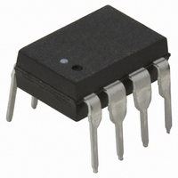
HCPL-3100 Avago Technologies US Inc., HCPL-3100 Datasheet - Page 7

HCPL-3100
Manufacturer Part Number
HCPL-3100
Description
OPTOCOUPLER GATE DRIVER 8-DIP
Manufacturer
Avago Technologies US Inc.
Datasheet
1.HCPL-3100.pdf
(14 pages)
Specifications of HCPL-3100
Voltage - Isolation
5000Vrms
Number Of Channels
1, Unidirectional
Current - Output / Channel
100mA
Propagation Delay High - Low @ If
2µs @ 10mA
Current - Dc Forward (if)
20mA
Input Type
DC
Output Type
Push-Pull, Totem-Pole
Mounting Type
Through Hole
Package / Case
8-DIP (0.300", 7.62mm)
Lead Free Status / RoHS Status
Contains lead / RoHS non-compliant
Other names
516-1119-5
Available stocks
Company
Part Number
Manufacturer
Quantity
Price
Company:
Part Number:
HCPL-3100
Manufacturer:
AGILENT
Quantity:
5 510
Company:
Part Number:
HCPL-3100
Manufacturer:
ELMOS
Quantity:
5 510
Notes:
1. Derate absolute maximum ratings with ambient temperatures as shown in Figures 11 and 12.
2. A bypass capacitor of 0.01 F or more is needed near the device between V
3. I
4. Device considered a two terminal device; pins 1-4 are shorted together and pins 5-8 are shorted together.
5. For devices with minimum V
6. The t
7. R
Switching Specifications (T
Propagation
Delay Time to
High Output
Level
Propagation
Delay Time to
Low Output
Level
Rise Time
Fall Time
Output High
Level Common
Mode Transient
Immunity
Output Low
Level Common
Mode Transient
Immunity
Packaging Characteristics
Input-Output Momentary
Withstand Voltage*
Resistance (Input-Output)
Capacitance (Input-Output)
*The Input-Output Momentary Withstand Voltage is a dielectric voltage rating that should not be interpreted as an input-output continuous voltage
rating. For the continuous voltage rating refer to the IEC/EN/DIN EN 60747-5-2 Insulation Characteristics Table (if applicable), your equipment level
safety specification, or Avago Application Note 1074, “Optocoupler Input-Output Endurance Voltage.”
7
characteristics.
applying an insulation test voltage
Transistor Gate/Base Drive Optocouplers.”
FLH
2
Parameter
limits the Q1 and Q2 peak currents. For more applications and circuit design information see Application Note “Power
represents the forward current when the output goes from low to high.
PLH
and t
Parameter
PHL
propagation delays are measured from the 50% level of the input pulse to the 50% level of the output pulse.
t
t
t
t
|CM
|CM
PLH
PHL
r
f
Sym.
H
L
|
|
ISO
HCPL-3100
HCPL-3101
HCPL-3100
HCPL-3101
HCPL-3100
HCPL-3101
HCPL-3100
HCPL-3101
HCPL-3100
HCPL-3101
specified at 5000 V rms, in accordance with UL 1577, each optocoupler is proof-tested by
Device
A
Sym.
V
R
C
ISO
= 25 C)
I-O
I-O
6000 V rms for one second (leakage current detection limit, I
5x10
Min.
5000
–
Min.
15
15
-
-
-
-
-
-
10
Typ.
10
1.2
Typ.
0.3
0.3
0.2
0.2
1
1
11
Max.
Max.
0.5
0.5
0.5
0.5
–
–
2
2
-
-
kV/ s
kV/ s
Units
V rms
Units
s
s
s
s
s
s
pF
CC
and GND when measuring output and transfer
I
I
I
I
I
I
I
I
I
I
I
F
F
F
F
F
F
F
F
F
F
F
= 10 mA
= 5 mA
= 10 mA
= 5 mA
= 10 mA
= 5 mA
= 10 mA
= 5 mA
= 10 mA
= 5mA
= 0 mA
RH = 40% to 60%
t = 1 min, T
V
RH = 40% to 60%
f = 1 MHz
I-O
= 500 V, T
Test Conditions
Test Conditions
A
V
V
R
C
V
V
V
= 25 C
A
CC
O1
CM
CC
O1
G
G
V
I-O
(peak),
02H
= 2.0 V
= 25 C
= 47 ,
= 3000 pF
= 24 V,
= 24 V,
= 24 V
= 24 V
= 1500 V
= V
200 A).
02L
Fig.
Fig.
25,
26,
27
10
9,
Note
Note
2, 6
4, 5
2
4
4


