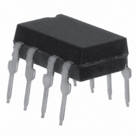
IL300 Vishay, IL300 Datasheet

IL300
Specifications of IL300
IL300GI
IL300GI
Available stocks
Related parts for IL300
IL300 Summary of contents
Page 1
... Audio Signal Interfacing Isolated Process Control Transducers Digital Telephone Isolation Description The IL300 Linear Optocoupler consists of an AlGaAs IRLED irradiating an isolated feedback and an output PIN photodiode in a bifurcated arrangement. The feedback photodiode captures a percentage of the LED’s flux and generates a control signal (I can be used to servo the LED drive current. This tech- nique compensates for the LED’ ...
Page 2
... R2)/(K1 • R1 The overall transfer gain is completely independent of the LED forward current. The IL300 transfer gain (K3) is expressed as the ratio of the output gain (K2) to the feedback gain (K1). This shows that the circuit gain becomes the product of the IL300 transfer gain times ...
Page 3
... Test condition Symbol P diss Test condition Symbol P tot T stg T amb = 25 °C R amb IO = 100 °C R amb IO IL300 Vishay Semiconductors Value Unit 160 mW 2.13 mW/° 250 mA 5.0 V 470 K/W 100 °C Value Unit 50 mA 0.65 mW/° 100 °C 1500 K/W Value Unit 210 mW 2 ...
Page 4
... IL300 Vishay Semiconductors Electrical Characteristics °C, unless otherwise specified amb Minimum and maximum values are testing requirements. Typical values are characteristics of the device and are the result of engineering evaluation. Typical values are for information only and are not part of the testing requirements. ...
Page 5
... Bin Categories: All IL300s are sorted into a K3 bin, indicated by an alpha character that is marked on the part. The bins range from "A" through "J". The IL300 is shipped in tubes of 50 each. Each tube contains only one category of K3. The category of the parts in the tube is marked on the tube label as well as on each individual part. ...
Page 6
... Figure 4. Servo Photocurrent vs. LED Current and Temperature 1000 100 1.3 1.4 iil300_05 Figure 5. Servo Photocurrent vs. LED Current and Temperature VISHAY Min Typ. Max 0.5 130 0°C 25°C 50°C 75° 100 LED Current - –15 V 0°C 25° ...
Page 7
... Figure 10. Transfer Gain vs. LED Current and Temperature 1.010 0°C 25°C 50°C 1.005 75°C 85°C 1.000 0.995 0.990 100 0 iil300_11 Figure 11. Normalized Transfer Gain vs. LED Current and IL300 Vishay Semiconductors 0°C 25°C 50°C 75°C 100°C Normalized to mA 25° 100 LED Current - mA Temperature 0° ...
Page 8
... Isolated Feedback Amplifier The IL300 was designed to be the central element of DC coupled isolation amplifiers. Designing the IL300 into an amplifier that provides a feedback control sig- nal for a line powered switch mode power is quite sim- ple, as the following example will illustrate ...
Page 9
... V a 17165 Document Number 83622 Rev. 1.5, 24-Mar-05 The value of R5 depends upon the IL300 Transfer Gain (K3 targeted unit gain device, however to minimize the part to part Transfer Gain variation, Infineon offers K3 graded into ± bins. R5 can determined using the following equation, ...
Page 10
... C 0.693 D 0.769 E 0.855 F 0.950 G 1.056 H 1.175 I 1.304 J 1.449 www.vishay.com 10 AC/DC XFORMER RECTIFIER SWITCH CONTROL MODE ISOLATED FEEDBACK TDA4918 Figure 17. Switching Mode Power Supply IL300 100 Max. 3 Typ. 0.623 0.59 0.693 0.66 0.769 0.73 0.855 0.81 0.950 0.93 1.056 1.00 1.175 1.11 1 ...
Page 11
... Figure 22. In order for the amplifier to respond to a signal that swings above and below ground, the LED must be pre biased from a separate source by using a voltage reference source (V these designs, R3 can be determined by the following equation. V ref1 IL300 Vishay Semiconductors 4.5 5.0 5.5 6.0 Vin - Input Voltage - PHASE 0 ...
Page 12
... R2 +Vcc 2 Vcc – 20pF –Vcc +Vref1 iil300_22 Table 2. Optolinear amplifiers Inverting Inverting Non-Inverting Non-Inverting Non-Inverting Inverting Non-Inverting Inverting Non-Inverting Inverting 17189 These amplifiers provide either an inverting or non- inverting transfer gain based upon the type of input and output amplifier. Table 2 shows the various con- figurations along with the specific transfer gain equa- tions ...
Page 13
... TYP . .180 (4.6) .160 (4.1) .0040 (.102) .0098 (.249) .315 (8.0) MIN. .331 (8.4) MIN. .406 (10.3) MAX. IL300 Vishay Semiconductors .100 (2.540) .050 (1.270) .010 (0.254) REF. ISO Method A .375 (9.53) .395 (10.03) .300 (7.62) ref. .012 (.30) typ. .020 (.51) .040 (1.02) 15° ...
Page 14
... IL300 Vishay Semiconductors Ozone Depleting Substances Policy Statement It is the policy of Vishay Semiconductor GmbH to 1. Meet all present and future national and international statutory requirements. 2. Regularly and continuously improve the performance of our products, processes, distribution and operating systems with respect to their impact on the health and safety of our employees and the public, as well as their impact on the environment ...
Page 15
... Vishay disclaims any and all liability arising out of the use or application of any product described herein or of any information provided herein to the maximum extent permitted by law. The product specifications do not expand or otherwise modify Vishay’ ...


