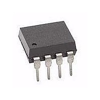
HCNR200#550 Avago Technologies US Inc., HCNR200#550 Datasheet - Page 11

HCNR200#550
Manufacturer Part Number
HCNR200#550
Description
OPTOCOUPLER ANALOG IEC 8-SMD
Manufacturer
Avago Technologies US Inc.
Datasheet
1.HCNR201-500E.pdf
(19 pages)
Specifications of HCNR200#550
Output Type
Linear Photovoltaic
Input Type
DC
Package / Case
8-SMD Gull Wing
Number Of Channels
1
Voltage - Isolation
5000Vrms
Current Transfer Ratio (min)
0.25% @ 10mA
Current Transfer Ratio (max)
0.75% @ 10mA
Current - Dc Forward (if)
25mA
Mounting Type
Surface Mount, Gull Wing
Current Transfer Ratio
0.25 % to 0.75 %
Forward Current
1 mA to 20 mA
Isolation Voltage
1414 Vrms
Minimum Forward Diode Voltage
1.2 V
Output Device
Photodiode
Configuration
1 Channel
Maximum Forward Diode Voltage
1.95 V
Maximum Reverse Diode Voltage
2.5 V
Maximum Input Diode Current
25 mA
Maximum Power Dissipation
60 mW
Maximum Operating Temperature
+ 100 C
Minimum Operating Temperature
- 55 C
Lead Free Status / RoHS Status
Contains lead / RoHS non-compliant
Voltage - Output
-
Current - Output / Channel
-
Vce Saturation (max)
-
Lead Free Status / RoHS Status
Lead free / RoHS Compliant, Contains lead / RoHS non-compliant
Available stocks
Company
Part Number
Manufacturer
Quantity
Price
Figure 11. Thermal derating curve dependence of safety limiting value
with case temperature per IEC/EN/DIN EN 60747-5-2.
Figure 12. Basic isolation amplifier.
Figure 13. Unipolar circuit topologies.
11
1000
900
800
700
600
500
400
300
200
100
0
0
V
V
V
V
IN
IN
IN
IN
25
T
S
– CASE TEMPERATURE – °C
P
I
S
R1
R1
50
S
I
INPUT CURRENT – mA
OUTPUT POWER – mV
PD1
PD1
CNR200 fig 11
75
C) NEGATIVE INPUT
A) POSITIVE INPUT
100
PD1
125
+
+
+
+
-
-
-
-
A1
A1
C1
150
LED
B) PRACTICAL CIRCUIT
A) BASIC TOPOLOGY
175
CNR200 fig 12
CNR200 fig 13
LED
R3
I
F
V
V
CC
CC
I
PD2
PD2
D) NEGATIVE OUTPUT
PD2
PD2
B) POSITIVE OUTPUT
R2
R2
+
+
+
+
-
-
-
-
A2
A2
C2
V
V
V
V
OUT
OUT
OUT
OUT


