HCPL-817 Avago Technologies US Inc., HCPL-817 Datasheet
HCPL-817
Specifications of HCPL-817
Available stocks


Related parts for HCPL-817


HCPL-817 Summary of contents
Page 1
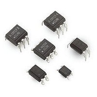
... Phototransistor Optocoupler High Density Mounting Type Data Sheet Lead (Pb) Free RoHS 6 fully compliant RoHS 6 fully compliant options available; -xxxE denotes a lead-free product Description The HCPL-817 contains a light emitting diode optically coupled to a phototransistor packaged in a 4-pin DIP package and available in wide-lead spacing option and lead bend SMD option. Input-output isolation voltage is 5000 Vrms. Response time, t and minimum CTR is 50% at input current of 5 mA. Schematic I ...
Page 2
... To order, choose a part number from the part number column and combine with the desired option from the option column to form an order entry. Example 1: HCPL-817-360E to order product of 300mil DIP-4 DC Gull Wing Surface Mount package in Tube packaging with 50%<CTR<600%, IEC/EN/DIN EN 60767-5-2 Safety Approval and RoHS compliant. Example 2: HCPL-817-50BE to order product of 300mil DIP-4 DC Gull Wing Surface Mount package in Tape and Reel packaging with 130%<CTR<260% and RoHS compliant. Option datasheets are available. Contact your Avago sales representative or authorized distributor for information. 2 Rank ‘C’ Rank ‘D’ Rank 200% 300% ‘L’ 50% < ...
Page 3
... RANK DIMENSIONS IN MILLIMETERS AND (INCHES) HCPL-817-060E DATE CODE A 817V LEAD FREE 6.5 ± 0.5 (0.256 ANODE RANK DIMENSIONS IN MILLIMETERS AND (INCHES) HCPL-817-W00E DATE CODE A 817 LEAD FREE 6.5 ± 0.5 (0.256 ANODE RANK DIMENSIONS IN MILLIMETERS AND (INCHES) 3 4.6 ± 0.5 (0.181) 3.5 ± ...
Page 4
... HCPL-817-300E DATE CODE A 817 LEAD FREE 6.5 ± 0.5 (0.256 ANODE RANK DIMENSIONS IN MILLIMETERS AND (INCHES) Solder Reflow Temperature Profile 250 ° C 217 ° C 200 ° C 150 ° ° 150 sec Time (sec) Note: Non-halide flux should be used. Absolute Maximum Ratings (T = 25˚ ...
Page 5
... Figure 2. Collector power dissipation vs. tempera- ture. HCPL-817 fig 2 Units Test Conditions µ KHz 0 µ mA ∞ mA µ µ 100 Ω L KHz R = 100 Ω, – Ω DC 500 60% R. MHz 25° 0 – FORWARD CURRENT – Figure 3. Collector-emitter saturation voltage vs. forward current. HCPL-817 fig 3 ...
Page 6
... T – AMBIENT TEMPERATURE – °C A Figure 8. Collector-emitter saturation voltage vs. temperature. HCPL-817 fig kΩ kΩ 100 Ω 0 – FREQUENCY – kHz Figure 11. Frequency response. HCPL-817 fig 25° – COLLECTOR-EMITTER VOLTAGE – Figure 6. Collector current vs. collector-emitter volt- age. ...
Page 7
Test Circuit for Response Time INPUT OUTPUT INPUT 10% OUTPUT 90 For product information and a complete list of distributors, please go to our website: Avago, ...