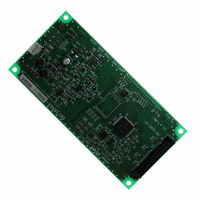
GU128X64-800B Noritake Company Inc, GU128X64-800B Datasheet - Page 10

GU128X64-800B
Manufacturer Part Number
GU128X64-800B
Description
MODULE VF GRAPHIC DISPLAY 128X64
Manufacturer
Noritake Company Inc
Series
800r
Datasheet
1.GU128X64-800B.pdf
(22 pages)
Specifications of GU128X64-800B
Viewing Area
83.10mm L x 41.50mm W
Display Format
21 x 8
Display Type
Graphic
Format
5 x 7 Dots
Voltage - Supply
5V
Number Of Dots
128 x 64
Operating Temperature
-40°C ~ 80°C
Lead Free Status / RoHS Status
Lead free / RoHS Compliant
Interface
-
Outline L X W X H
-
Character Size
-
Other names
286-1060
9.4 Display Clear (C/D= "1")
This command should always be applied at power on or reset. In the period of 1mS following the
issue of this command, the module requires internal processing and does not accept any
commands.
To clear the GRAM area, G1C or G0C bit must be asserted. By asserting HM bit, both data write position
address and display start position address which selected by G1C, G0C, DC also be reset.
HM = (1 or 0) equals (Initialize data write position address and display start position address or Not initialize).
9.3 Cont’d
Brightness levels are set by the following:
G1C= (1 or 0) equals (GRAM area 1 is cleared or GRAM area 1 not cleared)
G0C= (1 or 0) equals (GRAM area 0 cleared or GRAM area 0 not cleared)
GRAM area 1: X= 00H-7FH, Y=0H – 7H (Display data write position address)
GRAM area 2: X= 00H-7FH, Y=8H – FH (Display data write position address)
MSB
< --------------------------- > < ---------------------------- >
0
BW3
0
0
0
0
0
0
0
0
1
1
1
1
1
1
1
1
Command Select
1
BW2
0
0
0
0
1
1
1
1
0
0
0
0
1
1
1
1
0
This command clears the GRAM.
BW1
0
0
1
1
0
0
1
1
0
0
1
1
0
0
1
1
1
G1C
BW0
0
1
0
1
0
1
0
1
0
1
0
1
0
1
0
1
Clear Control Code
G0C
1
Brightness Level
100%(Light)
LSB
HM
6%(Dark)
94%
87%
81%
75%
69%
62%
56%
50%
44%
37%
31%
25%
19%
12%
GU128X64-800B
9


