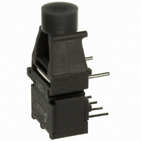
HFBR-1528Z Avago Technologies US Inc., HFBR-1528Z Datasheet - Page 13

HFBR-1528Z
Manufacturer Part Number
HFBR-1528Z
Description
XMITTER FIBER OPTIC 600NM 10MBD
Manufacturer
Avago Technologies US Inc.
Specifications of HFBR-1528Z
Wavelength
600nm
Voltage - Forward (vf) Typ
2.02V
Current - Dc Forward (if)
1A
Voltage - Dc Reverse (vr) (max)
5V
Connector Type
Versatile Link
Function
Ideal for solving problems with voltage isolation/insulation, EMI/RFI immunity or data security.
Product
Transmitter
Data Rate
10 MBd
Diode Capacitance
60 pF
Maximum Rise Time
13 ns (Typ)
Maximum Fall Time
10 ns (Typ)
Operating Supply Voltage
4.75 V to 5.25 V
Maximum Operating Temperature
+ 85 C
Minimum Operating Temperature
- 40 C
Data Rate Max
10Mbps
Forward Current If
80mA
Forward Voltage
1.67V
Reverse Voltage Vr
5V
Data Transmission Distance
50ft
Wavelength Typ
660nm
Msl
MSL 4 - 72 Hours
Fiber Material
Plastic
Rohs Compliant
Yes
Lead Free Status / RoHS Status
Lead free / RoHS Compliant
Capacitance
-
Spectral Bandwidth
-
Lead Free Status / Rohs Status
Lead free / RoHS Compliant
For Use With
Plastic Optical Fiber, Hard Clad Silica
Lead Free Status / RoHS Status
Lead free / RoHS Compliant, Lead free / RoHS Compliant
Other names
516-2047
Available stocks
Company
Part Number
Manufacturer
Quantity
Price
Company:
Part Number:
HFBR-1528Z
Manufacturer:
AVAGO
Quantity:
784
Absolute Maximum Ratings
Notes:
1. 1.6 mm below seating plane.
2. Recommended operating range between 10 and 750 mA.
3. 1 μs pulse, 20 μs period.
HFBR-15X2Z/15X4Z Transmitters
CATHODE
Transmitter Electrical/Optical Characteristics
For forward voltage and output power vs. drive current graphs.
Note:
1. Rise and fall times are measured with a voltage pulse driving the transmitter and a series connected 50 Ω load. A wide bandwidth optical to
13
Parameter
Storage Temperature
Operating Temperature
Lead Soldering Cycle
Forward Input Current
Reverse Input Voltage
Parameter
Transmitter
Output
Optical
Power
Output Optical Power
Temperature Coefficient
Peak Emission Wavelength
Forward Voltage
Forward Voltage
Temperature Coefficient
Effective Diameter
Numerical Aperture
Reverse Input Breakdown
Voltage
Diode Capacitance
Rise Time
Fall Time
ANODE
electrical waveform analyzer, terminated to a 50 Ω input of a wide bandwidth oscilloscope, is used for this response time measurement.
All HFBR-15XXZ LED transmitters are classified as IEC 825-1 Accessible Emission Limit (AEL) Class 1 based upon the current proposed
draft scheduled to go into effect on January 1, 1997. AEL Class 1 LED devices are considered eye safe. Contact your Avago sales repre-
sentative for more information.
N.C.
N.C.
1
2
3
4
HFBR-15X2Z
HFBR-15X4Z
8 DO NOT CONNECT
5 DO NOT CONNECT
Time
Temp.
Symbol
ΔP
ΔV
O
V
NA
D
C
P
P
T
V
F
t
t
PK
BR
/ΔT
F
O
r
f
T
T
/ΔT
T
0°C to 70°C unless otherwise specified.
–13.6
–11.2
–17.8
–15.5
Symbol
Min.
1.45
5.0
I
I
V
FPK
Fdc
T
T
BR
A
S
–0.85
–1.37
1.67
11.0
Typ.
660
0.5
86
80
40
1
Note: Pins 5 and 8 are for mounting and retaining purposes only.
Do not electrically connect these pins.
Pin #
1
2
3
4
5
8
Min.
–40
–40
Max.
–4.5
–5.1
–4.5
–5.1
2.02
mV/°C
%/°C
Units
dBm
dBm
mm
nm
pF
ns
ns
V
V
1000
Max.
+85
+85
260
Function
Anode
Cathode
Open
Open
Do not connect
Do not connect
10
80
5
I
I
I
I
I
I
T
V
10% to 90%,
I
Fdc
Fdc
Fdc
Fdc
Fdc
Fdc
F
A
F
= 60 mA
= 25°C
= 0, f = 1 MHz
= 60 mA
= 60 mA, 25°C
= 60 mA
= 60 mA, 25°C
= 60 mA
= 10 μA,
Conditions
Units
mA
sec
°C
°C
°C
V
Reference
Note 1
Note 2, 3
Note 1
Fig. 11
Ref.


