TOTX147L(F,T) Toshiba, TOTX147L(F,T) Datasheet - Page 3
TOTX147L(F,T)
Manufacturer Part Number
TOTX147L(F,T)
Description
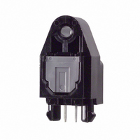
XMITTER MODULE FIBER OPTIC SHUT
Manufacturer
Toshiba
Datasheet
1.TOTX147LFT.pdf
(6 pages)
Specifications of TOTX147L(F,T)
Lead Free Status / RoHS Status
Lead free / RoHS Compliant
Other names
TOTX147L
TOTX147L
TOTX147LFT
TOTX147L
TOTX147LFT


7. Board layout hole pattern
8. Precautions during use
(1)
(2)
(3)
(4)
(5)
Maximum rating
The maximum ratings are the limit values which must not be exceeded during operation of device.
None of these rating value must not be exceeded. If the maximum rating value is exceeded, the
characteristics of devices may never be restored properly. In extreme cases, the device may be
permanently damages.
Lifetime of light emitters
If an optical module is used for a long period of time, degeneration in the characteristics will mostly
be due to a lowering of the fiber output power (Pf). This is caused by the degradation of the optical
output of the LEDs used as the light source. The cause of degradation of the optical output of the
LEDs may be defects in wafer crystallization or mold resin stress. The detailed causes are, however,
not clear.
The lifetime of light emitters is greatly influenced by the operating conditions and the environment in
which it is used as well as by the lifetime characteristics unique to the device type. Thus, when a light
emitting device and its operating conditions determined, Toshiba recommend that lifetime
characteristics be checked.
Depending on the environment conditions, Toshiba recommend that maintenance such as regular
checks of the amount of optical output in accordance with the condition of operating environment.
Soldering
Optical modules are comprised of internal semiconductor devices. However, in principle, optical
modules are optical components. During soldering, ensure that flux does not contact with the emitting
surface or the detecting surface. Also ensure that proper flux removal is conducted after soldering.
Some optical modules come with shutter system. The shutter system is used to avoid malfunction
when the optical module is not in use. Note that it is not dust or waterproof.
As mentioned before, optical modules are optical components. Thus, in principle, soldering where
there may be flux residue and flux removal after soldering is not recommended. Toshiba recommend
that soldering be performed without the optical module mounted on the board. Then, after the board
has been cleaned, the optical module should be soldered on to the board manually.
If the optical module cannot be soldered manually, use non- halogen (chlorine- free) flux and make
sure, without cleaning, there is no residue such as chlorine. This is one of the ways to eliminate the
effects of flux. In such a cases, be sure to check the devices’reliability.
Vibration and shock
This module is plastic sealed and has its wire fixed by resin. This structure is relatively resistant to
vibration and shock. In actual equipment, there are sometimes cases in which vibration, shock, or
stress is applied to soldered parts or connected parts, resulting in lines cut. A care must be taken in
the design of equipment which will be subject to high levels of vibration.
Support pins
The optical transmission module TOTX147L(F,T) has support pins in order to fix itself to the PCB
temporary. Please make the hole for these pins in the PCB under the condition described in board
layout hole pattern.
(Recommendation)
3
Unit: mm
Tolerance: ±0.05 mm
Recommended PCB thickness: 1.6 mm
TOTX147L(F,T)
2004-02-02
Related parts for TOTX147L(F,T)
Image
Part Number
Description
Manufacturer
Datasheet
Request
R

Part Number:
Description:
TRANSMITTER, FIBRE OPTIC
Manufacturer:
Toshiba
Datasheet:

Part Number:
Description:
TRANSMITTER MODULE FIBER OPTIC
Manufacturer:
Toshiba
Datasheet:

Part Number:
Description:
Toshiba Semiconductor [TOSHIBA IGBT Module Silicon N Channel IGBT]
Manufacturer:
TOSHIBA Semiconductor CORPORATION
Datasheet:
Part Number:
Description:
TOSHIBA GTR MODULE SILICON NPN TRIPLE DIFFUSED TYPE
Manufacturer:
TOSHIBA Semiconductor CORPORATION
Datasheet:
Part Number:
Description:
TOSHIBA GTR Module Silicon N Channel IGBT
Manufacturer:
TOSHIBA Semiconductor CORPORATION
Datasheet:
Part Number:
Description:
TOSHIBA Intelligent Power Module Silicon N Channel IGBT
Manufacturer:
TOSHIBA Semiconductor CORPORATION
Datasheet:
Part Number:
Description:
TOSHIBA INTELLIGENT POWER MODULE SILICON N CHANNEL LGBT
Manufacturer:
TOSHIBA Semiconductor CORPORATION
Datasheet:
Part Number:
Description:
TOSHIBA IGBT Module Silicon N Channel IGBT
Manufacturer:
TOSHIBA Semiconductor CORPORATION
Datasheet:
Part Number:
Description:
TOSHIBA GTR MODULE SILICON N−CHANNEL IGBT
Manufacturer:
TOSHIBA Semiconductor CORPORATION
Datasheet:
Part Number:
Description:
TOSHIBA Intelligent Power Module Silicon N Channel IGBT
Manufacturer:
TOSHIBA Semiconductor CORPORATION
Datasheet:
Part Number:
Description:
TOSHIBA GTR Module Silicon N Channel IGBT
Manufacturer:
TOSHIBA Semiconductor CORPORATION
Datasheet:
Part Number:
Description:
TOSHIBA INTELLIGENT POWER MODULE
Manufacturer:
TOSHIBA Semiconductor CORPORATION
Datasheet:
Part Number:
Description:
TOSHIBA Intelligent Power Module Silicon N Channel IGBT
Manufacturer:
TOSHIBA Semiconductor CORPORATION
Datasheet:
Part Number:
Description:
TOSHIBA Intelligent Power Module Silicon N Channel IGBT
Manufacturer:
TOSHIBA Semiconductor CORPORATION
Datasheet:
Part Number:
Description:
TOSHIBA IGBT Module Silicon N Channel IGBT
Manufacturer:
TOSHIBA Semiconductor CORPORATION
Datasheet: