XPERDO-L1-R250-00501 Cree Inc, XPERDO-L1-R250-00501 Datasheet

LED RED 615NM XLAMP WTR CLR SMD

XPERDO-L1-R250-00501

Manufacturer Part Number
XPERDO-L1-R250-00501
Description
LED RED 615NM XLAMP WTR CLR SMD
Manufacturer
Cree Inc
Series
Xlamp® XP-Er

Specifications of XPERDO-L1-R250-00501

Viewing Angle
130°
Color
Orange-Red
Current - Test
350mA
Luminous Flux @ Current - Test
56.8lm
Current - Max
700mA
Lumens @ Current - Max
107lm
Lumens/watt @ Current - Test
77lm/W
Voltage - Forward (vf) Typ
2.1V
Wavelength
615nm
Lens Style/size
Round, 2.6mm
Mounting Type
Surface Mount
Package / Case
0.14" L x 0.14" W x 0.08" H (3.45mm x 3.45mm x 2mm)
Led Color
Red Orange
Luminous Flux @ Test
62lm
Wavelength Typ
620nm
Forward Current @ Test
350mA
Forward Current If Max
700mA
Forward Voltage @ Test
2.1V
Lead Free Status / RoHS Status
Lead free / RoHS Compliant
For Use With
876-1003 - LM3406 LED DRIVER EVAL BOARD
Lead Free Status / RoHS Status
Lead free / RoHS Compliant, Lead free / RoHS Compliant
Other names
XPERDO-L1-R250-00501TR
Cree
Data Sheet
The XLamp color XP-E LED combines the proven performance and reliability of the
XLamp XR color LED in a package with 80% smaller footprint. The XLamp XP-E LED
continues Cree’s history of innovation in LEDs for lighting applications with wide
viewing angle, symmetrical package, unlimited floor life and electrically neutral
thermal path.
Cree XLamp LEDs bring high performance to a wide range of lighting applications,
including color-changing, architectural, stage and studio, transportation, commercial
and emergency-vehicle lighting.
FEATURES
Table of Contents
Flux Characteristics (T
Characteristics ........................................................................................................................................ 2
Relative Spectral Power Distribution ........................................................................................................... 3
Relative Flux vs. Junction Temperature (I
Electrical Characteristics (T
Thermal Design ....................................................................................................................................... 4
Relative Flux vs. Current (T
Typical Spatial Distribution ........................................................................................................................ 5
Reflow Soldering Characteristics ................................................................................................................ 6
Notes ..................................................................................................................................................... 6
Mechanical Dimensions (T
Tape and Reel ......................................................................................................................................... 8
Packaging ............................................................................................................................................... 9
Bin- and Order-Code Format ................................................................................................................... 10
Performance Groups – Brightness ............................................................................................................ 10
Performance Groups – Dominant Wavelength ............................................................................................ 10
Standard Order Codes and Bins ............................................................................................................... 11
This is a preliminary, non-binding product specification provided for informational purposes only and is
subject to change without notice. This product is unreleased and is provided “as is” without warranty.
Guaranteed minimum flux order codes
Maximum drive current: 1000 mA
Industry’s lowest thermal resistance: 9°C/W
Unlimited floor life at ≤30°/85% Rh
®
XLamp
J
= 25°C) - Color ...................................................................................................... 2
A
J
J
= 25°C) ........................................................................................................... 7
= 25°C) .......................................................................................................... 4
= 25°C) ......................................................................................................... 5
®
XP-E Royal Blue LEDs
August 19, 2009
F
= 350 mA) ................................................................................... 3
Preliminary
www.cree.com/xlamp
Wide viewing angle
Reflow solderable – JEDEC J-STD-020C
compatible
Electrically neutral thermal path
RoHS-compliant
1

Related parts for XPERDO-L1-R250-00501

XPERDO-L1-R250-00501 Summary of contents

Page 1

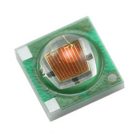
Cree XLamp XP-E Royal Blue LEDs ® ® Data Sheet The XLamp color XP-E LED combines the proven performance and reliability of the XLamp XR color LED in a package with 80% smaller footprint. The XLamp XP-E LED continues Cree’s ...

Page 2

Flux Characteristics (T = 25°C) - Color J The following table provides the base order code for XLamp XP-E Royal Blue LEDs important to note that the base order codes listed here are a subset of the total ...

Page 3

Relative Spectral Power Relative Spectral Power Distribution 100 400 Relative Flux vs. Junction Temperature (I 100% 90% 80% 70% 60% 50% 40% 30% 20% 10 Copyright © 2009 Cree, Inc. All rights reserved. ...

Page 4

Electrical Characteristics (T 1000 900 800 700 600 500 400 300 200 100 0 0.0 0.5 Thermal Design The maximum forward current is determined by the thermal re- sistance between the LED junction and ambient crucial for the ...

Page 5

Relative Flux vs. Current (T 250 200 150 100 Typical Spatial Radiation Pattern Typical Spatial Distribution -100 -80 Copyright © 2009 Cree, Inc. All rights reserved. The information in this document is subject to change without notice. ...

Page 6

Reflow Soldering Characteristics In testing, Cree has found XLamp XP-E LEDs to be compatible with JEDEC J-STD- 020C, using the parameters listed below general guideline, Cree recommends that users follow the recommended solder- ing profile provided by the ...

Page 7

Mechanical Dimensions (T 3.45 3.45 Top View .50 .50 .40 .50 3.30 RECOMMENDED PCB SOLDER PAD Copyright © 2009 Cree, Inc. All rights reserved. The information in this document is subject to change without notice. Cree, the Cree logo, and ...

Page 8

Tape and Reel 4.0±.1 1.75±.10 +.3 12.0 .0 END Trailer 160mm (min) of empty pockets sealed with tape (20 pockets min.) 7" Copyright © 2009 Cree, Inc. All rights reserved. The information in this document is subject to change without ...

Page 9

Humidity Indicator Card (inside bag) Packaging Label with Cree Bin CREE Bin Code Code, Qty, Lot # & Barcode Label Label with Cree Bin CREE Bin Code Code, Qty, Lot # & Barcode Label Patent Label Patent Label Copyright © ...

Page 10

Bin- and Order-Code Format Bin codes and order codes are configured in the following manner: Order Code Series XPE = XP-E Optical configuration (default = L1) Kit number SSSCCC-BD-HHHH-NNNNN Internal code Color ROY = Royal Blue Performance Groups – Brightness ...

Page 11

Standard Order Codes and Bins The following tables list standard kit numbers and performance bins. Kit numbers completely describe an order code’s dominant-wavelength range and or radiant-flux range. Min. Radiant Flux (mW) @ 350 mA* Group Flux (mW) 14 350 ...

Related keywords