591-2001-013F Dialight, 591-2001-013F Datasheet - Page 14
591-2001-013F
Manufacturer Part Number
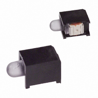
591-2001-013F
Description
LED PRISM 3MM RA HIEFF RED SMT
Manufacturer
Dialight
Series
591r
Datasheets
1.CY7C21701KV18-400BZXC.pdf
(24 pages)
2.591-2401-013F.pdf
(2 pages)
3.591-2401-013F.pdf
(1 pages)
Specifications of 591-2001-013F
Color
Red
Voltage Rating
2.0V
Current
20mA
Lens Type
Diffused, White
Lens Style/size
Round, 3mm, T-1
Configuration
Single
Mounting Type
Surface Mount, Right Angle
Led Size
3 mm
Illumination Color
Red
Lens Color/style
Red Diffused
Luminous Intensity
5 mcd
Operating Current
30 mA
Operating Voltage
2.6 V
Viewing Angle
40 deg
Lead Free Status / RoHS Status
Lead free / RoHS Compliant
Other names
350-1785-2
5912001013F
5912001013F
Available stocks
Company
Part Number
Manufacturer
Quantity
Price
Company:

Part Number:
591-2001-013F
Manufacturer:
DLT
Quantity:
48 000


TAP AC Switching Characteristics
Over the Operating Range
TAP Timing and Test Conditions
Figure 2
Notes
Document Number: 001-57344 Rev. *A
t
t
t
t
Setup Times
t
t
t
Hold Times
t
t
t
Output Times
t
t
15. t
16. Test conditions are specified using the load in TAP AC Test Conditions. t
TCYC
TF
TH
TL
TMSS
TDIS
CS
TMSH
TDIH
CH
TDOV
TDOX
Parameter
CS
and t
shows the TAP timing and test conditions.
CH
refer to the setup and hold time requirements of latching data from the boundary scan register.
TCK Clock Cycle Time
TCK Clock Frequency
TCK Clock HIGH
TCK Clock LOW
TMS Setup to TCK Clock Rise
TDI Setup to TCK Clock Rise
Capture Setup to TCK Rise
TMS Hold after TCK Clock Rise
TDI Hold after Clock Rise
Capture Hold after Clock Rise
TCK Clock LOW to TDO Valid
TCK Clock LOW to TDO Invalid
TDO
Test Mode Select
TMS
Test Clock
TCK
Test Data In
TDI
Test Data Out
TDO
[15, 16]
Z
0
= 50Ω
(a)
GND
0.9V
Figure 2. TAP Timing and Test Conditions
C
50Ω
L
= 20 pF
Description
[16]
t
TMSS
t
TDIS
R
/t
F
= 1 ns.
t
t
TDOV
TH
0V
t
t
TL
TMSH
t
TDIH
1.8V
t
ALL INPUT PULSES
TDOX
0.9V
t
TCYC
Min
50
20
20
5
5
5
5
5
5
0
CY7C21701KV18
Max
20
10
Page 14 of 24
MHz
Unit
ns
ns
ns
ns
ns
ns
ns
ns
ns
ns
ns
[+] Feedback
Related parts for 591-2001-013F
Image
Part Number
Description
Manufacturer
Datasheet
Request
R

Part Number:
Description:
LED PRISM 3MM HI EFF RED SMD
Manufacturer:
Dialight
Datasheet:

Part Number:
Description:
LED PRISM 3MM RA HIEFF RED SMT
Manufacturer:
Dialight
Datasheet:

Part Number:
Description:
LED PRISM 3MM HI EFF RED SMT
Manufacturer:
Dialight
Datasheet:

Part Number:
Description:
LED PRISM 3MM RND HI EFF RED SMD
Manufacturer:
Dialight
Datasheet:

Part Number:
Description:
LED PRISM 3MM SQ HI EFF RED SMD
Manufacturer:
Dialight
Datasheet:

Part Number:
Description:
LED PRISM 3MM SQ HI EFF RED SMD
Manufacturer:
Dialight
Datasheet:
Part Number:
Description:
LED PRISM 3MM RND HI EFF RED SMD
Manufacturer:
Dialight
Datasheet:
Part Number:
Description:
LED PRISM 3MM SQ HI EFF RED SMD
Manufacturer:
Dialight
Datasheet:

Part Number:
Description:
INDICATOR, LED PCB, 3MM, RED, 2V
Manufacturer:
Dialight
Datasheet:
Part Number:
Description:
LED PRISM 3MM RA ALGAAS RED SMT
Manufacturer:
Dialight
Datasheet:
Part Number:
Description:
LED PRISM 3MM GREEN
Manufacturer:
Dialight
Datasheet:

Part Number:
Description:
LED PRISM 3MM RT ANG YELLOW SMT
Manufacturer:
Dialight
Datasheet:
Part Number:
Description:
LED PRISM 3MM RT ANG GREEN SMT
Manufacturer:
Dialight
Datasheet: