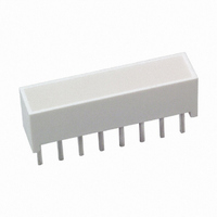
HLMP-2450 Avago Technologies US Inc., HLMP-2450 Datasheet - Page 15

HLMP-2450
Manufacturer Part Number
HLMP-2450
Description
LED LT BAR 19.05X3.81MM SGL YLW
Manufacturer
Avago Technologies US Inc.
Datasheet
1.HLMP-2500.pdf
(16 pages)
Specifications of HLMP-2450
Color
Yellow (x 4)
Voltage Rating
2.1V
Current
25mA
Lens Style/size
Rectangle, 19.05mm x 3.81mm
Configuration
Single
Mounting Type
Through Hole
Product
LED Light Bars
Illumination Color
Yellow
Luminous Intensity
38 mcd
Light Bar Length
19.05 mm
Supply Voltage
2.1 V
Supply Current
20 mA
Wavelength
585 nm
Current, Forward, Peak
60 mA
Light Emitting Area, Size
19.05 x 3.81
Power Dissipation
85 mW
Temperature, Operating
-40 to +85 °C
Temperature, Soldering
250 °C @ 3 Sec.
Voltage, Breakdown, Reverse
15 V (Typ.)
Voltage, Forward
2 V⁄ LED (Typ)
Voltage, Reverse
15 V ⁄LED (Typ)
Wavelength, Dominant
585 nm (Typ.)
Wavelength, Peak
583 nm (Typ.)
Led Configuration
Bar
Led Color
Yellow
Forward Voltage
2.1V
Forward Current If
20mA
Display Size
19.05mm X 3.81mm
Leaded Process Compatible
Yes
Rohs Compliant
Yes
Lead Free Status / RoHS Status
Lead free / RoHS Compliant
Lens Type
-
Lead Free Status / Rohs Status
Lead free / RoHS Compliant
Other names
516-1247-5
Available stocks
Company
Part Number
Manufacturer
Quantity
Price
Company:
Part Number:
HLMP-2450
Manufacturer:
AVAGO
Quantity:
400
Company:
Part Number:
HLMP-2450
Manufacturer:
AVAGO
Quantity:
40 000
Company:
Part Number:
HLMP-2450-EF000
Manufacturer:
FAIRCHIL
Quantity:
40 000
15
Electrical
These light bars are composed of
two, four, or eight light emitting
diodes, with the light from each
LED optically scattered to form
an evenly illuminated light
emitting surface.
The anode and cathode of each
LED is brought out by separate
pins. This universal pinout
arrangement allows the LEDs to
be connected in three possible
configurations: parallel, series, or
series parallel. The typical
forward voltage values can be
scaled from Figures 4 and 9.
These values should be used to
calculate the current limiting
resistor value and typical power
consumption. Expected maximum
V
and maximum power dissipation,
Optical
The radiation pattern for these
light bar devices is approximately
Lambertian. The luminous
sterance may be calculated using
one of the two following formulas:
L
L
v
v
F
8.89 mm x 8.89 mm
8.89 mm x 3.81 mm
8.89 mm x 19.05 mm
3.81 mm x 19.05 mm
(cd/m
(footlamberts) =
values for driver circuit design
Size of Light
Emitting
2
Area
) =
I
A (m
v
(cd)
2
)
A (ft
I
v
67.74 x 10
33.87 x 10
135.48 x 10
72.85 x 10
Sq. Metres
(cd)
2
)
Surface Area
–6
–6
–6
–6
may be calculated using the
following V
AlGaAs Red HLCP-X100 series
V
For: I
V
For: 20 mA
HER (HLMP-2300/2600/2900),
Yellow (HLMP-2400/2700/2900)
and Green (HLMP-2500/2800/
2900) series
V
For: 5 mA
V
For: I
The maximum power dissipation
can be calculated for any pulsed
or DC drive condition. For DC
operation, the maximum power
Refresh rates of 1 kHz or faster
provide the most efficient
operation resulting in the maxi-
mum possible time average
luminous intensity.
The time average luminous
intensity may be calculated using
the relative efficiency character-
istic of Figure 3 or 8, I
adjusted for operating ambient
temperature. The time average
luminous intensity at T
calculated as follows:
729.16 x 10
364.58 x 10
1458.32 x 10
781.25 x 10
F
F
F
F
MAX = 1.8 V + I
MAX = 2.0 V + I
MAX = 1.6 + I
MAX = 1.8 + I
Sq. Feet
Peak
Peak
F
–6
–6
–6
20 mA
20 mA
MAX models:
–6
I
Peak
I
Peak
Peak
Peak
Peak
Peak
20 mA
(50 )
(40 )
45 mA
A
(20 )
(10 )
PEAK
= 25 C is
, and
dissipation is the product of the
maximum forward voltage and the
maximum forward current. For
pulsed operation, the maximum
power dissipation is the product
of the maximum forward voltage
at the peak forward current times
the maximum average forward
current. Maximum allowable
power dissipation for any given
ambient temperature and thermal
resistance (R
mined by using Figure 2 or 7. The
solid line in Figure 2 or 7 (R
600/538 C/W) represents a typical
thermal resistance of a device
socketed in a printed circuit
board. The dashed lines represent
achievable thermal resistances
that can be obtained through
improved thermal design. Once
the maximum allowable power
dissipation is determined, the
maximum pulsed or DC forward
current can be calculated.
I
where:
Example:
v TIME AVG
I
For HLMP-2735 series
I
TEST
v TIME AVG
I
PEAK
= 3 mA for AlGaAs Red
= 1.18 at I
=
(HLMP-X000 series)
20 mA for HER,
Yellow and Green
(HLMP-2XXX series)
=
[ ]
= 25 mcd
[ ]
J-A
I
I
AVG
TEST
) can be deter-
12 mA
20 mA
PEAK
( I
= 48 mA
PEAK
(1.18) (35 mcd)
) (I
J-A
v
of
Data Sheet)


