3314G-1-101E Bourns Inc., 3314G-1-101E Datasheet - Page 4
3314G-1-101E
Manufacturer Part Number
3314G-1-101E
Description
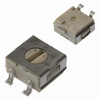
POT 100 OHM 4MM SQ CERMET SMD
Manufacturer
Bourns Inc.
Series
3314 - Sealedr
Type
Trimmerr
Datasheet
1.3314J-1-501E.pdf
(4 pages)
Specifications of 3314G-1-101E
Tolerance
±20%
Number Of Turns
Single
Temperature Coefficient
±100ppm/°C
Resistance (ohms)
100
Power (watts)
0.25W, 1/4W
Adjustment Type
Top Adjustment
Mounting Type
Surface Mount
Resistive Material
Cermet
Package / Case
Square - 0.177" L x 0.177" W x 0.100" H (4.50mm x 4.50mm x 2.54mm)
Resistance In Ohms
100
Resistance
100 Ohms
Power Rating
0.25 Watt (1/4 Watt)
Operating Temperature Range
- 55 C to + 125 C
Element Type
Cermet
Dimensions
4.5 mm W x 4.50 mm L x 2.55 mm H
Product
Trimmers
Termination Style
SMD/SMT
Taper
Linear
Tolerance (+ Or -)
20%
Technology
Cermet
Mounting Style
Surface Mount
Operating Temp Range
-55C to 125C
Failure Rate
Not Required
Shaft Diameter (mm)
2.45mm
Product Diameter (mm)
Not Requiredmm
Product Length (mm)
5mm
Product Height (mm)
2.55mm
Product Depth (mm)
6.2mm
Product Type
Single Turn
Adjustment
Top Slot
Lead Free Status / RoHS Status
Lead free / RoHS Compliant
Lead Free Status / RoHS Status
Lead free / RoHS Compliant, Lead free / RoHS Compliant
Other names
3314G-101ETR
Available stocks
Company
Part Number
Manufacturer
Quantity
Price
Company:

Part Number:
3314G-1-101E
Manufacturer:
BOURNS
Quantity:
12 000
Part Number:
3314G-1-101E
Manufacturer:
BOURNS/伯恩斯
Quantity:
20 000


3314Z-1-(RC) E
(Cross Slot)
3314Z-GA4-(RC) E
(Straight Slot)
3314Z-3
(Reverse Marking, Straight Slot)
3314Z-4-(RC) E
(Reverse Marking, Cross Slot)
Product Dimensions
3314 - 4 mm Square Trimpot
ROTOR POSITIONED AS SHOWN
WITHIN ± 22° OF CENTERLINE
OF TERMINAL 2
ROTOR POSITIONED AS SHOWN
WITHIN ± 22° OF CENTERLINE
OF TERMINAL 2
ROTOR POSITIONED AS SHOWN
WITHIN ± 22° OF CENTERLINE
OF TERMINAL 2
ROTOR POSITIONED AS SHOWN
WITHIN ± 22° OF CENTERLINE
OF TERMINAL 2
1
1
1
1
2
2
2
2
3
3
3
3
(0.50)
TOLERANCES: ±
3314Z
Common Dimensions
RECOMMENDED PCB LAYOUT
1.27
®
(.125)
3.18
CCW
Trimming Potentiometer
(0.051)
(.137)
(.197)
3.48
5.01
1.3
DIMENSIONS:
1
(0.10)
2.54
(.079)
2.01
(0.10)
CLOCKWISE
2.54
(.010)
(0.047)
0.25
(0.051)
1.19
1.29
(.024)
0.61
2
(INCHES)
EXCEPT WHERE NOTED
WIPER
MM
(.008)
0.21
(0.121)
(0.227)
3.08
5.76
(0.131)
Customers should verify actual device performance in their specifi c applications.
3.32
(.079)
2.01
(0.219)
3
5.56
(.079)
2.01
(.010)
0.26
CW
(.038)
0.96
TAPE
(Z Style)
REEL
* Embossed Tape Designator "E"
** Embossed Tape Designator "G"
Meets EIA specification 481.
(.079)
(0.59 +.004/-0.0)
2.0
(.512 ± .020)
(See How To Order chart for further information.)
(.016)
Packaging Specifi cations
1.5 + 0.1/-0.0
0.40
13.0 ± .51
Specifi cations are subject to change without notice.
(.070) ± .010)
DIA.
DIA.
(.157)
1.78 ± .25
MAX.
4.0
(13.00 ± .079)
177.8 ± 2.03
(7.00 ± .080)
(.069)
330.2 ± 2.0
1.75
(.236)
6.0
(.630 ± 0.012)
5° MAX.
DIA.**
16.00 ± 0.3
DIA.*
(.827 ± .031)
21.01 ± .79
(.295)
7.5
(.646 + .079/ - .00)
DIA.
16.4 + 2.0/ -.00
(.217)
5.5
(.472)
DIA.
R
12.0
B
(.020)
(2.330 ± .080)
(.105 ± .010)
0.5
59.18 ± 2.03
REV. 08/10
(.059)
2.67 ± .25
1.5
TYP.
(.358)
9.1
MIN.
Related parts for 3314G-1-101E
Image
Part Number
Description
Manufacturer
Datasheet
Request
R

Part Number:
Description:
POT, TRIM, 20OHM, 1 TURN, 20%, SMD
Manufacturer:
Bourns Inc.
Datasheet:

Part Number:
Description:
POT 1K OHM 4MM SQ CERMET SMD
Manufacturer:
Bourns Inc.
Datasheet:
Part Number:
Description:
POT 10K OHM 4MM SQ CERMET SMD
Manufacturer:
Bourns Inc.
Datasheet:
Part Number:
Description:
POT 5K OHM 4MM SQ CERMET SMD
Manufacturer:
Bourns Inc.
Datasheet:
Part Number:
Description:
POT 50K OHM 4MM SQ CERMET SMD
Manufacturer:
Bourns Inc.
Datasheet:
Part Number:
Description:
POT 500 OHM 4MM SQ CERMET SMD
Manufacturer:
Bourns Inc.
Datasheet:
Part Number:
Description:
POT 2K OHM 4MM SQ CERMET SMD
Manufacturer:
Bourns Inc.
Datasheet:
Part Number:
Description:
POT 20K OHM 4MM SQ CERMET SMD
Manufacturer:
Bourns Inc.
Datasheet:
Part Number:
Description:
POT 200 OHM 4MM SQ CERMET SMD
Manufacturer:
Bourns Inc.
Datasheet:
Part Number:
Description:
POT 100K OHM 4MM SQ CERMET SMD
Manufacturer:
Bourns Inc.
Datasheet:
Part Number:
Description:
POT 25K OHM 4MM SQ CERMET SMD
Manufacturer:
Bourns Inc.
Datasheet:

Part Number:
Description:
TRIMPOT 50 OHM 4MM CERMET SMD
Manufacturer:
Bourns Inc.
Datasheet:
Part Number:
Description:
TRIMPOT 10 OHM 4MM CERMET SMD
Manufacturer:
Bourns Inc.
Datasheet:
Part Number:
Description:
POT, TRIMMER, 1MOHM, 1 TURN, SMD
Manufacturer:
Bourns Inc.
Datasheet:
Part Number:
Description:
POT 200K OHM 4MM SQ CERMET SMD
Manufacturer:
Bourns Inc.
Datasheet: