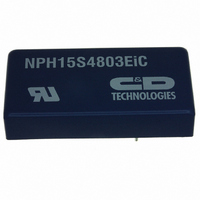
NPH15S4803EIC Murata Power Solutions Inc, NPH15S4803EIC Datasheet - Page 4

NPH15S4803EIC
Manufacturer Part Number
NPH15S4803EIC
Description
CONV DC/DC 15W 48VIN 3.4VOUT DIP
Manufacturer
Murata Power Solutions Inc
Series
NPH15Sr
Type
Isolatedr
Specifications of NPH15S4803EIC
Number Of Outputs
1
Output
3.4V
Power (watts)
15W
Mounting Type
Through Hole
Voltage - Input
36 ~ 75V
Package / Case
6-DIP Module
1st Output
3.4 VDC @ 4.4A
Size / Dimension
1.97" L x 0.98" W x 0.39" H (50mm x 24.9mm x 9.9mm)
Power (watts) - Rated
15W
Operating Temperature
-40°C ~ 110°C
Efficiency
83%
Approvals
cUL, UL
Output Power
0.015 W
Input Voltage Range
36 V to 75 V
Input Voltage (nominal)
48 V
Output Voltage (channel 1)
3.4 V
Output Current (channel 1)
4.4 mA
Isolation Voltage
1.5 KV
Package / Case Size
DIP
Product
Isolated
Lead Free Status / RoHS Status
Lead free / RoHS Compliant
3rd Output
-
2nd Output
-
4th Output
-
Lead Free Status / Rohs Status
Lead free / RoHS Compliant
Other names
811-1640-5
Available stocks
Company
Part Number
Manufacturer
Quantity
Price
APPLICATION NOTES (continued)
TECHNICAL NOTES
ISOLATION VOLTAGE
‘Hi Pot Test’, ‘Flash Tested’, ‘Withstand Voltage’, ‘Proof Voltage’, ‘Dielectric Withstand Voltage’ & ‘Isolation Test Voltage’ are all terms that relate to the same thing, a test voltage,
applied for a specifi ed time, across a component designed to provide electrical isolation, to verify the integrity of that isolation.
Murata Power Solutions NPH15S series of DC/DC converters are all 100% production tested at their stated isolation voltage. This is 1500 VDC for 1 second.
A question commonly asked is, “What is the continuous voltage that can be applied across the part in normal operation?”
The NPH15S series has been recognized by Underwriters Laboratory, both input and output should normally be maintained within SELV limits i.e. less than 42.4V peak, or 60VDC.
The isolation test voltage represents a measure of immunity to transient voltages and the part should never be used as an element of a safety isolation system. The part could be
expected to function correctly with several hundred volts offset applied continuously across the isolation barrier; but then the circuitry on both sides of the barrier must be regarded
as operating at an unsafe voltage and further isolation/insulation systems must form a barrier between these circuits and any user-accessible circuitry according to safety standard
requirements.
REPEATED HIGH-VOLTAGE ISOLATION TESTING
It is well known that repeated high-voltage isolation testing of a barrier component can actually degrade isolation capability, to a lesser or greater degree depending on materi-
als, construction and environment. While manufactured parts can withstand several times the stated test voltage, the isolation capability does depend on the wire insulation. Any
material, including this enamel (typically polyurethane) is susceptible to eventual chemical degradation when subject to very high applied voltages thus implying that the number of
tests should be strictly limited. We therefore strongly advise against repeated high voltage isolation testing, but if it is absolutely required, that the voltage be reduced by 20% from
specifi ed test voltage.
www.murata-ps.com
SYNCHRONIZATION
The converter frequency may be synchronised to an external frequency by connecting a negative going pulse to the SS pin. The drive signal is typically
8V to 12V amplitude and 100ns to 200ns duration. A suitable circuit consists of a CMOS timer (TLC555) connected as an oscillator or as a pulse shaper.
Its logic output (not the discharge output) should be connected via a 4.7nF capacitor to the converter pin. The synchronised frequency is above the free
running value. However, the free running frequency can be lowered, so that sychronisation may include frequencies near or below the natural value. An
example of a practical circuit is shown below, which uses a zener diode to lower the natural frequency. Several converters of this family may be syn-
chronised from the same reference provided the waveform can be maintained by the use of an adequate driver circuit. If the rise time is more than 20ns,
for example, synchronisation may not be achieved over the specifi ed frequency range.
For best effi ciency, set the frequency within the specifi ed range of its natural state.
Technical enquiries email: mk@murata-ps.com, tel: +44 (0)1908 615232
Isolated 15W Single Output DC/DC Converters
2010-03-01 KDC_NPH15SC.F03 Page 4 of 8
NPH15S Series


